- Profilo corpo principale
- Gomito
- Gomito piatto con collegamento diretto cilindro
- Metodo di controllo
- Tipo giunto
- Materiale corpo principale
- Resina
- PBT
- Ambiente d'esercizio, applicazioni
- Con manopola
- Opzione controdado
- Leva di bloccaggio scorrimento
- Con blocco a pressione
- Applicable Tube O.D. inch size(inch)
- Body Size
- Handle Material
- Direzione finestra indicatore
- Tipo
- CAD
- 2D
- 3D
- Giorni di spedizione est.
- Tutti
- Entro 26 giorni lavorativi
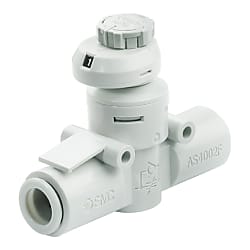
AS*2FS, Regolatore di flusso con indicatore, Tipo in linea (AS1002FS2-07)
Informazioni sul prodotto
Speed Controller With Indicator Window Allowing Flow Rate To Be Controlled Numerically

The numerical indication of flow rate helps to reduce labor time and setting errors.
Speed Controller With Indicator, In-Line Type, AS-FS Series Specifications
| Model | Applicable tubing outer diameter | |||||||||||
|---|---|---|---|---|---|---|---|---|---|---|---|---|
| Metric size | Inch Size | |||||||||||
| 3.2 | 4 | 6 | 8 | 10 | 12 | 1/8 " | 5/32 " | 1/4 " | 5/16 " | 3/8 " | 1/2 " | |
| AS1002FS□ | ● | ● | ● | - | - | - | ● | ● | ● | - | - | - |
| AS2002FS□ | - | ● | ● | - | - | - | - | ● | ● | - | - | - |
| AS2052FS□ | - | - | ● | ● | - | - | - | - | ● | ● | - | - |
| AS3002FS□ | - | - | ● | ● | ● | ● | - | - | ● | ● | ● | - |
| AS4002FS□ | - | - | - | - | ● | ● | - | - | - | - | ● | ● |
Model
| Usable fluids | Air |
|---|---|
| Proof pressure | 1.5 MPa |
| Max. operating pressure | 1 MPa |
| Min. operating pressure | 0.1 MPa |
| Ambient and fluid temperature | -5 to 60℃ (no freezing) |
| Applicable tubing material | Nylon, soft nylon, polyurethaneNote), FEP, PFA |
Specifications
Note) Use caution at the max. operating pressure when using soft nylon or polyurethane tubing.
| Model | AS1002FS□ | AS2002FS□ | AS2052FS□ | AS3002FS□ | AS4002FS□ | |||||||||
|---|---|---|---|---|---|---|---|---|---|---|---|---|---|---|
| Tube outer diameter | Metric size | ø3.2 | ø4 | ø6 | ø4 | ø6 | ø6 | ø8 | ø6 | ø8 | ø10 | ø12 | ø10 | ø12 |
| Inch Size | ø1/8 " | ø5/32 " | ø1/4 " | ø5/32 " | ø1/4 " | ø1/4 " | ø5/16 " | ø1/4 " | ø5/16 " | ø3/8 " | - | ø3/8 " | ø1/2 " | |
| C values: Sonic conductance dm3/(s·bar) | Free flow | 0.3 | 0.4 | 0.6 | 0.4 | 0.6 | 1.0 | 1.2 | 1.1 | 1.6 | 2.2 | 2.6 | 2.4 | 3.5 |
| Controlled flow | 0.3 | 0.4 | 0.6 | 1.0 | 1.2 | 1.3 | 1.9 | 2.7 | 3.3 | 2.8 | 4.1 | |||
| b values: Critical pressure ratio | Free flow | 0.3 | 0.2 | 0.3 | 0.1 | 0.2 | 0.2 | 0.3 | 0.2 | |||||
| Controlled flow | 0.2 | 0.3 | 0.4 | 0.2 | 0.2 | 0.3 | 0.1 | 0.2 | 0.1 | 0.2 | ||||
Features of this product

Improved reproducibility of flow rate:Stable knob position when fully closed (zero flow rate) onto the contact face stopper (rotating stopper).
Minimal flow rate variation depending on the number of knob rotations.

Examples of mounting variations.
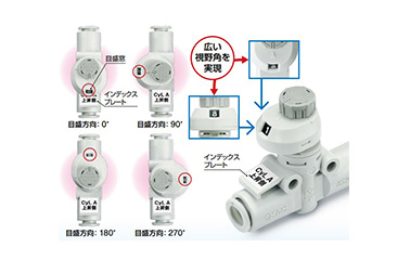
4 indicator window directions offer improved visibility.
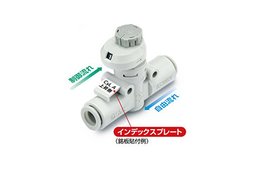
Identification by index plate: It is possible to identify the product when multiple controllers are mounted and identify the flow direction by attaching an identification label.
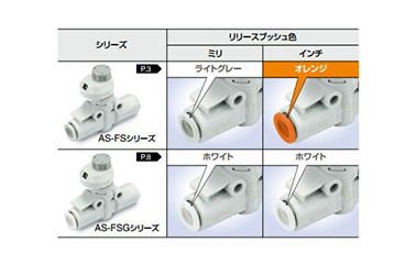
Identification by color.
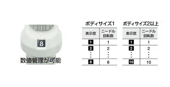
Flow rate can be controlled numerically with the indicator window.

In-line / Brass / Stainless steel
Larger push-lock type knob
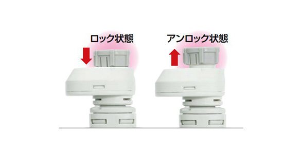
Improves needle lock operation.
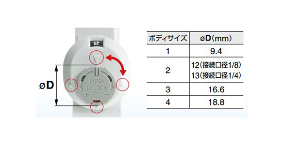
The larger knob and marking of every 90° mark allows for easier operation.
Outline drawing and dimensions for this product
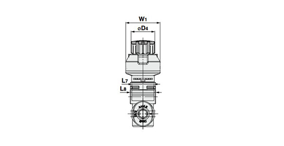
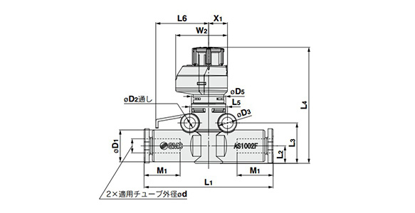
Speed Controller With Indicator, In-Line Type, AS-FS Series dimensional drawing
Indicator window direction: 0° front view
Right side view
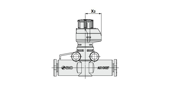
Indicator window direction: 180° side view
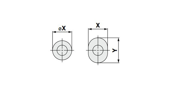
Release button dimensions
Applies to: ø3.2, 4, 6 (3.2, 4, 6 cm) ø1/8, 5/32 (1/8, 5/32 inch)
| Model | Applicable tubing outer diameter ød | D1 | Release button dimensions | D2 | D3 | D4 | D5 | L1 | L2 | L3 | L4 | L5 | L6 | L7 | L8 | M1 | W1 | W2 | X1 | X2 | Weight (g) | ||
|---|---|---|---|---|---|---|---|---|---|---|---|---|---|---|---|---|---|---|---|---|---|---|---|
| øX (X) | Y | MAX. | MIN. | ||||||||||||||||||||
| AS1002FS□-23 | 3.2 | 8.4 | 6.7 | 9.5 | 3.3 | 5.5 | 9.4 | 10 | 36.6 | 5.1 | 11.8 | 36.4 | 33.9 | 11 | 15.4 | 8.8 | 10.1 | 13.5 | 13.6 | 15.1 | 5.5 | 9.6 | 5.2 |
| AS1002FS□-04 | 4 | 9.3 | 7.7 | 10 | 37.6 | 5.5 | |||||||||||||||||
| AS1002FS□-06 | 6 | 11.6 | 9.7 | 12 | 40.1 | 6.1 | 12.8 | 37.4 | 34.9 | 12.3 | 6.6 | ||||||||||||
| AS2002FS□-04 | 4 | 9.3 | 7.7 | 10 | 3.3 | 5.5 | 12 | 12 | 41.3 | 6.3 | 13.4 | 44.5 | 43 | 12.6 | 17 | 10.5 | 12.3 | 13.5 | 20 | 21.5 | 6.5 | 15 | 9.5 |
| AS2002FS□-06 | 6 | 11.6 | 9.7 | 12 | 43.1 | 10.4 | |||||||||||||||||
| AS2052FS□-06 | 6 | 12.8 | 11.5 | - | 4.3 | 7.8 | 13 | 16 | 54.2 | 7.6 | 17.2 | 49.0 | 47.6 | 17 | 22.5 | 12 | 16.1 | 17 | 21.5 | 24 | 7.8 | 16.2 | 16 |
| AS2052FS□-08 | 8 | 15.2 | 13.5 | - | 57.2 | 8.5 | 18.1 | 49.9 | 48.5 | 19 | 18.4 | ||||||||||||
| AS3002FS□-06 | 6 | 13.2 | 11.5 | - | 4.5 | 8 | 16.6 | 20 | 60 | 9.8 | 21.7 | 55.7 | 54.3 | 21.8 | 25 | 12 | 20.5 | 17 | 24.5 | 28.5 | 9.3 | 19.2 | 23.8 |
| AS3002FS□-08 | 8 | 15.2 | 13.5 | - | 65 | 19 | 26 | ||||||||||||||||
| AS3002FS□-10 | 10 | 18.5 | 16.5 | - | 70.4 | 21 | 30.6 | ||||||||||||||||
| AS3002FS□-12 | 12 | 20.9 | 18.5 | - | 76 | 10.9 | 22.8 | 56.8 | 55.4 | 22.1 | 22 | 34.2 | |||||||||||
| AS4002FS□-10 | 10 | 18.5 | 16.5 | - | 4.3 | 8 | 18.8 | 26 | 76.9 | 11.3 | 23.7 | 64.3 | 62.7 | 28 | 33 | 14 | 26.2 | 21 | 26 | 29 | 10 | 19 | 42.5 |
| AS4002FS□-12 | 12 | 21.7 | 18.5 | - | 81.3 | 22 | 47.9 | ||||||||||||||||
Metric size
| Model | Applicable tubing outer diameter ød | D1 | Release button dimensions | D2 | D3 | D4 | D5 | L1 | L2 | L3 | L4 | L5 | L6 | L7 | L8 | M1 | W1 | W2 | X1 | X2 | Weight (g) | ||
|---|---|---|---|---|---|---|---|---|---|---|---|---|---|---|---|---|---|---|---|---|---|---|---|
| øX (X) | Y | MAX. | MIN. | ||||||||||||||||||||
| AS1002FS□-01 | 1/8 " | 8.4 | 6.7 | 9.5 | 3.3 | 5.5 | 9.4 | 10 | 36.6 | 5.1 | 11.8 | 36.4 | 33.9 | 11 | 15.4 | 8.8 | 10.1 | 13.5 | 13.6 | 15.1 | 5.5 | 9.6 | 5.2 |
| AS1002FS□-03 | 5/32 " | 9.3 | 7.7 | 10 | 37.6 | 5.5 | |||||||||||||||||
| AS1002FS□-07 | 1/4 " | 12 | 10.9 | - | 40.1 | 6.2 | 12.9 | 37.5 | 35 | 12.8 | 6.7 | ||||||||||||
| AS2002FS□-03 | 5/32 " | 9.3 | 7.7 | 10 | 3.3 | 5.5 | 12 | 12 | 41.3 | 6.3 | 13.4 | 44.5 | 43 | 12.6 | 17 | 10.5 | 12.3 | 13.5 | 20 | 21.5 | 6.5 | 15 | 9.5 |
| AS2002FS□-07 | 1/4 " | 12 | 10.9 | - | 43.2 | 6.5 | 13.6 | 44.7 | 43.2 | 12.8 | 10.6 | ||||||||||||
| AS2052FS□-07 | 1/4 " | 13.2 | 12 | - | 4.3 | 7.8 | 13 | 16 | 53.4 | 7.6 | 17.2 | 49 | 47.6 | 17 | 22.5 | 12 | 16.1 | 17 | 21.5 | 24 | 7.8 | 16.2 | 16.4 |
| AS2052FS□-09 | 5/16 " | 15.2 | 13.5 | - | 57.2 | 8.5 | 18.1 | 49.9 | 48.5 | 19 | 18.4 | ||||||||||||
| AS3002FS□-07 | 1/4 " | 13.2 | 12 | - | 4.5 | 8 | 16.6 | 20 | 59 | 9.8 | 21.7 | 55.7 | 54.3 | 21.8 | 25 | 12 | 20.5 | 17 | 24.5 | 28.5 | 9.3 | 19.2 | 23.6 |
| AS3002FS□-09 | 5/16 " | 15.2 | 13.5 | - | 65 | 19 | 26 | ||||||||||||||||
| AS3002FS□-11 | 3/8 " | 18.5 | 16 | - | 69.8 | 21 | 38.1 | ||||||||||||||||
| AS4002FS□-11 | 3/8 " | 18.5 | 16 | - | 4.3 | 8 | 18.8 | 26 | 76.9 | 11.3 | 23.7 | 64.3 | 62.7 | 28 | 33 | 14 | 26.2 | 21 | 26 | 29 | 10 | 19 | 50.2 |
| AS4002FS□-13 | 1/2 " | 21.7 | 20 | - | 81.3 | 22 | 57.4 | ||||||||||||||||
Inch Size
- *See the manufacturer's catalog for types and model numbers other than the above.
Ulteriori informazioni
Informazioni di base
Speed controller made by SMC Corporation.
[Features]
· The numerical indication of flow rate helps to reduce labor time and setting errors. Allows numerical indication to be checked using the indicator window.
· 4 indicator window directions offer improved visibility
Attenzione
- See catalog for specification details.
- Product images may be representative images. Refer to the catalog for shape details.
