- Lavori di manutenzione: questa pagina non sarà disponibile dalle ore 3:00 21/4/2024 alle ore 0:00 (CET) 22/4/2024 per lavori di manutenzione al server. Ci scusiamo per questo inconveniente.
JAH, giunto snodato, carico pesante
[Features]
· A floating joint can absorb any "off-centering" or "loss of parallel accuracy" present between the cylinder and the driven body.
· Centering is unnecessary.
· A high level of machining accuracy is unnecessary.
· Dramatically reduces installation time.
· Compact and suitable for high tensile stresses.
· Long service life (with dust-proof cover).
· Rotating angle: ±5°
(i)Nota
- See catalog for specification details.
- Product images may be representative images. Refer to the catalog for details.
Codice componente
Qui sono indicati i codici componente
correlati al prodotto ricercato
Floating Joint: Heavy Load Type JAH Series Specifications
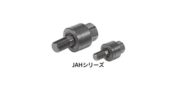
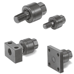
JAH Series external appearance
- Operating pressure: hydraulic cylinder 7 MPa or less
- Mounting: basic type, flange type, foot type
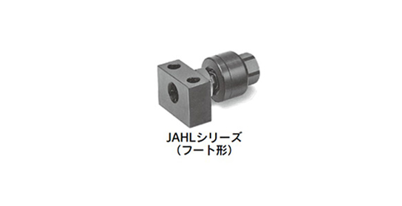
JAHL Series (foot type) external appearance
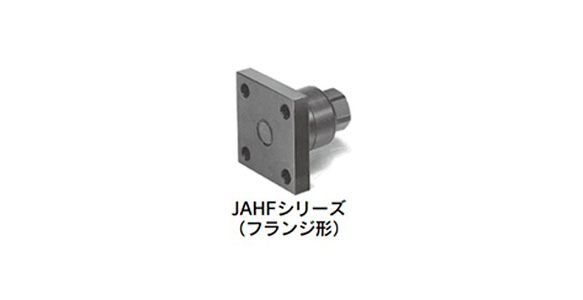
JAHF Series (flange type) external appearance
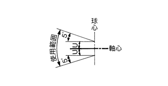
JAH Series operating range
| Model | Compatible bore size (mm) | Compatible cylinder nominal thread size | Maximum operating tension and compression force N | Allowable eccentricity U (mm) | Rotating angle | Ambient temperature | ||
|---|---|---|---|---|---|---|---|---|
| Basic type | Flange type | Foot | ||||||
| JAH□40-16-150 | 40 | M16 ×; 1.5 | 11,000 | 9,000 | 9,000 | 0.25 | ±5 ° | -5 to 60°C |
| JAH□50-20-150 | 50 | M20 ×; 1.5 | 18,000 | 14,000 | 14,000 | 2 | ||
| JAH□63-24-150 | 63 | M24 ×; 1.5 | 28,000 | 22,000 | 22,000 | 2 | ||
| JAH□80-30-150 | 80 | M30 ×; 1.5 | 54,000 | 36,000 | 36,000 | 2.5 | ||
| JAH□100-39-150 | 100 | M39 ×; 1.5 | 71,000 | 55,000 | 55,000 | 3 | ||
| JAH□100-48-150 | 100 | M48 ×; 1.5 | 71,000 | 55,000 | 55,000 | 3 | ||
| JAH□63-24-200 | 63 | M24 ×; 2 | 28,000 | 22,000 | 22,000 | 2 | ±5 ° | |
| JAH□80-30-200 | 80 | M30 ×; 2 | 54,000 | 36,000 | 36,000 | 2.5 | ||
| JAH□100-42-300 | 100 | M42 ×; 3 | 71,000 | 55,000 | 55,000 | 3 | ||
Diagram / Parts List
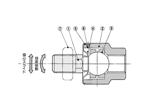
JAH Series Diagram
*See the manufacturer's catalog regarding replacement parts.
| Number | Number | Material | Note |
|---|---|---|---|
| 1 | Stud | Chrome molybdenum steel | Dyed black |
| 2 | Case | Carbon steel | Black zinc chromated |
| 3 | Ring | Chrome molybdenum steel | - |
| 4 | Cap | Carbon steel | Black zinc chromated |
| 5 | Dust cover | Synthetic rubber | - |
| 6 | Set screw | Carbon steel | Zinc chromate |
| 7 | Rod end nut | Carbon steel | Zinc chromate |
| 8 | Flange | Rolled steel plate | Black zinc chromated |
| 9 | Foot | Rolled steel plate | Black zinc chromated |
Basic Type / JAH40 to 100 dimensional drawing
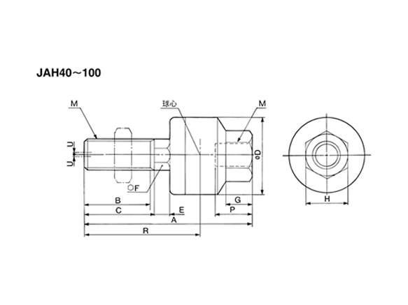
JAH40 to 100 dimensional drawing
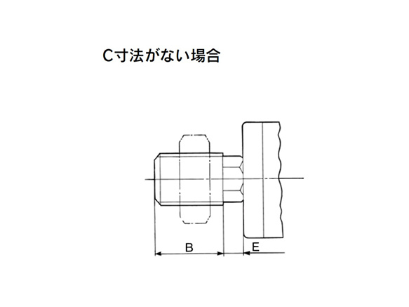
Without C-dimension
(Unit: mm)
Heavy‑Load Type / Hydraulic: Up to 7 MPa
| Compatible bore size | Model | M | A | B | C | D | E | F | G | H | Center of sphere R | |
|---|---|---|---|---|---|---|---|---|---|---|---|---|
| Nominal diameter | Pitch | |||||||||||
| 40 | JAH40-16-150 | 16 | 1.5 | 85.5 | 22 | 25 | 50 | 9.5 | 19 | 16 | 32 | 52.5 |
| 50 | JAH50-20-150 | 20 | 1.5 | 101 | 28 | 31 | 59.5 | 11.5 | 24 | 16 | 32 | 64 |
| 63 | JAH63-24-150 | 24 | 1.5 | 120 | 32 | 35 | 66 | 13 | 27 | 20 | 41 | 74 |
| 80 | JAH80-30-150 | 30 | 1.5 | 152 | 42 | 45 | 79 | 14 | 30 | 22 | 46 | 94.5 |
| 100 | JAH100-39-150 | 39 | 1.5 | 178 | 52 | 55 | 96 | 16 | 36 | 24 | 55 | 112 |
| 100 | JAH100-48-150 | 48 | 1.5 | 191 | 61 | - | 96 | 16 | 36 | 28 | 70 | 118 |
| Compatible bore size | Model | Maximum thread depth P | Allowable eccentricity U | Maximum operating tension and compression force N | Weight kg |
|---|---|---|---|---|---|
| 40 | JAH40-16-150 | 18 | 1.25 | 11,000 | 0.58 |
| 50 | JAH50-20-150 | 18 | 2 | 18,000 | 1.08 |
| 63 | JAH63-24-150 | 24 | 2 | 28,000 | 1.5 |
| 80 | JAH80-30-150 | 38 | 2.5 | 54,000 | 2.7 |
| 100 | JAH100-39-150 | 42 | 3 | 71,000 | 4.8 |
| 100 | JAH100-48-150 | 49 | 3 | 71,000 | 5.4 |
| Compatible bore size | Model | M | A | B | C | D | E | F | G | H | Center of sphere R | |
|---|---|---|---|---|---|---|---|---|---|---|---|---|
| Nominal diameter | Pitch | |||||||||||
| 63 | JAH63-24-200 | 24 | 2 | 120 | 32 | 35 | 66 | 13 | 27 | 20 | 41 | 74 |
| 80 | JAH80-30-200 | 30 | 2 | 152 | 41 | 45 | 79 | 14 | 30 | 22 | 46 | 94.5 |
| 100 | JAH100-42-300 | 42 | 3 | 178 | 55 | - | 96 | 16 | 36 | 24 | 55 | 112 |
| Compatible bore size | Model | Maximum thread depth P | Allowable eccentricity U | Maximum operating tension and compression force N | Weight kg |
|---|---|---|---|---|---|
| 63 | JAH63-24-200 | 24 | 2 | 28,000 | 1.5 |
| 80 | JAH80-30-200 | 38 | 2.5 | 54,000 | 2.7 |
| 100 | JAH100-42-300 | 42 | 3 | 71,000 | 4.8 |
Precautions
Mounting
- *When screwing the male threads of the rod into the female threads of the socket or the case, make sure that the rod does not bottom out. If the floating joint is used with its rod bottomed out, the stud will not be able to float, causing damage. For the screw-in depth of the female threads, refer to the dimensions in the manufacturer's catalog. As a rule, after the rod bottoms out, back off 1 to 2 turns.
- *The dust cover may stick to the stud. Move the dust cover at the base of the stud with your fingers, or twist the stud right and left gently to free it. When screwing the stud and socket or case into a driven body, make sure to remove the dust cover. Screwing without removing dust cover may break the dust cover.
- *When using a floating joint to connect the cylinder rod to a driven body, secure it in place by applying a torque that is appropriate for the thread size. Also, if there is a risk of loosening during operation, take measures to prevent loosening, such as using a locking pin or thread adhesive. In the event that the connected portion becomes loose, the driven body might lose control or fall off, etc., leading to equipment damage or injury to personnel.
- *This product is not a rotary joint. It cannot be used for rotational applications.
- *Be sure to use the cushion mechanism of the cylinder or a buffer mechanism such as a shock absorber to prevent impact force being applied to the floating joint when stopping the driven body. If there is no buffer mechanism, an impact force is generated that may cause the floating joint to exceed its maximum tensile and compressive force level.
Maintenance
- *Do not use if the product has been disassembled. High-strength adhesive is applied to the portion of the connection that is threaded to prevent it from loosening. The product must therefore not be disassembled. If the product is forcefully disassembled, it could lead to damage.
- *Black zinc chromate treatment is applied to the material surfaces of the case, flange and foot. In rare circumstances, white deposits may occur on the surface.
Other precautions
- *See the manufacturer's catalog for information other than the above.
- *Pictures are of representational models.
| Codice componente |
Prezzo unitario standard
| Quantità minima d'ordine | Sconto volumi elevati | Filettatura di collegamento nominale M (mm) | Filettatura di collegamento nominale p (mm) | Tipo di attacco, lato pezzo | Testa metallica | Disallineamento U ammesso (mm) | Dimensione foro applicabile (ø) | Filettatura nominale cilindro applicabile | Opzione | |
|---|---|---|---|---|---|---|---|---|---|---|---|---|
61.27 € | 1 | 4 giorni | M10–M18 | 1–1.75 | Filettature | Non fornito | 1.25 | 40 | M16 × 1.5 | Assente | ||
76.61 € | 1 | 18 giorni | M10–M18 | 1–1.75 | Filettature | Non fornito | 1.25 | 40 | M16 × 1.5 | Specifiche per alte temperature (da -5 a +100°C) | ||
67.79 € | 1 | 33 giorni | M20–M26 | 1–1.75 | Filettature | Non fornito | 2 | 50 | M20 × 1.5 | Assente | ||
78.90 € | 1 | 26 giorni | M20–M26 | 1–1.75 | Filettature | Non fornito | 2 | 50 | M20 × 1.5 | Specifiche per alte temperature (da -5 a +100°C) | ||
92.52 € | 1 | 26 giorni | M20–M26 | 1–1.75 | Filettature | Non fornito | 2 | 63 | M24 × 1.5 | Assente | ||
108.02 € | 1 | 26 giorni | M20–M26 | 1–1.75 | Filettature | Non fornito | 2 | 63 | M24 × 1.5 | Specifiche per alte temperature (da -5 a +100°C) | ||
99.79 € | 1 | 26 giorni | M20–M26 | 2–2.5 | Filettature | Non fornito | 2 | 63 | M24 × 2 | Assente | ||
234.73 € | 1 | 4 giorni | M30–M36 | 1–1.75 | Filettature | Non fornito | 2.5 | 80 | M30 × 1.5 | Assente | ||
242.65 € | 1 | 26 giorni | M30–M36 | 2–2.5 | Filettature | Non fornito | 2.5 | 80 | M30 × 2 | Assente | ||
306.94 € | 1 | 26 giorni | M38 to M39 | 1–1.75 | Filettature | Non fornito | 3 | 100 | M39 × 1.5 | Assente | ||
314.85 € | 1 | 26 giorni | M40–M45 | 2.5 or more | Filettature | Non fornito | 3 | 100 | M42 × 3 | Assente | ||
442.34 € | 1 | Preventivo | M48 | 1–1.75 | Filettature | Non fornito | 3 | 100 | M48 × 1.5 | Assente | ||
77.97 € | 1 | 26 giorni | M10–M18 | 1–1.75 | Foro | Bulloneria flangia | 1.25 | 40 | M16 × 1.5 | Assente | ||
84.31 € | 1 | 4 giorni | M20–M26 | 1–1.75 | Foro | Bulloneria flangia | 2 | 50 | M20 × 1.5 | Assente | ||
100.42 € | 1 | 26 giorni | M20–M26 | 1–1.75 | Foro | Bulloneria flangia | 2 | 50 | M20 × 1.5 | Specifiche per alte temperature (da -5 a +100°C) | ||
109.02 € | 1 | 26 giorni | M20–M26 | 1–1.75 | Foro | Bulloneria flangia | 2 | 63 | M24 × 1.5 | Assente | ||
116.29 € | 1 | 26 giorni | M20–M26 | 2–2.5 | Foro | Bulloneria flangia | 2 | 63 | M24 × 2 | Assente | ||
288.90 € | 1 | Preventivo | M30–M36 | 1–1.75 | Foro | Bulloneria flangia | 2.5 | 80 | M30 × 1.5 | Assente | ||
296.89 € | 1 | Preventivo | M30–M36 | 2–2.5 | Foro | Bulloneria flangia | 2.5 | 80 | M30 × 2 | Assente | ||
379.16 € | 1 | Preventivo | M38 to M39 | 1–1.75 | Foro | Bulloneria flangia | 3 | 100 | M39 × 1.5 | Assente | ||
387.10 € | 1 | 26 giorni | M40–M45 | 2.5 or more | Foro | Bulloneria flangia | 3 | 100 | M42 × 3 | Assente | ||
482.98 € | 1 | Preventivo | M48 | 1–1.75 | Foro | Bulloneria flangia | 3 | 100 | M48 × 1.5 | Assente | ||
77.97 € | 1 | 26 giorni | M10–M18 | 1–1.75 | Foro | Bulloneria base | 1.25 | 40 | M16 × 1.5 | Assente | ||
84.31 € | 1 | 26 giorni | M20–M26 | 1–1.75 | Foro | Bulloneria base | 2 | 50 | M20 × 1.5 | Assente | ||
109.02 € | 1 | 26 giorni | M20–M26 | 1–1.75 | Foro | Bulloneria base | 2 | 63 | M24 × 1.5 | Assente | ||
116.31 € | 1 | 26 giorni | M20–M26 | 2–2.5 | Foro | Bulloneria base | 2 | 63 | M24 × 2 | Assente | ||
288.90 € | 1 | 26 giorni | M30–M36 | 1–1.75 | Foro | Bulloneria base | 2.5 | 80 | M30 × 1.5 | Assente | ||
379.16 € | 1 | 26 giorni | M38 to M39 | 1–1.75 | Foro | Bulloneria base | 3 | 100 | M39 × 1.5 | Assente | ||
387.10 € | 1 | 26 giorni | M40–M45 | 2.5 or more | Foro | Bulloneria base | 3 | 100 | M42 × 3 | Assente |
Loading...
Informazioni di base
| Tipo | Giunti flottanti | Cilindro usato | Cilindri idraulici | Tipo di attacco, lato cilindro | Maschiati |
|---|---|---|---|---|---|
| Materiale corpo principale | Acciaio al carbonio | Materiale prigioniero | Acciaio al cromo-molibdeno | Disallineamento angolare V ammesso(deg) | ±5 |
Configura
Proprietà di base
-
Filettatura di collegamento nominale M(mm)
- M10–M18
- M20–M26
- M30–M36
- M40–M45
- M38 to M39
- M48
-
Filettatura di collegamento nominale p(mm)
- 1–1.75
- 2–2.5
- 2.5 or more
-
Tipo di attacco, lato pezzo
-
 Filettature
 -
 Foro
Foro
-
-
Testa metallica
- Non fornito
- Bulloneria flangia
- Bulloneria base
-
Disallineamento U ammesso(mm)
-
Dimensione foro applicabile(ø)
- 40
- 50
- 63
- 80
- 100
-
Filettatura nominale cilindro applicabile
- M16 × 1.5
- M20 × 1.5
- M24 × 1.5
- M24 × 2
- M30 × 1.5
- M30 × 2
- M39 × 1.5
- M42 × 3
- M48 × 1.5
-
Opzione
- Specifiche per alte temperature (da -5 a +100°C)
- Assente
-
Tipo
- JAH
-
Filtrare per tipo dati CAD
- 2D
- 3D


Filtrare per giorni di spedizione standard
-
- Tutti gli articoli
- 4 giorni o meno
- 18 giorni o meno
- 26 giorni o meno
- 33 giorni o meno
Attributi opzionali
- Product images may be representative images. Refer to the catalog for details.
- Specifiche e dimensioni di alcuni componenti potrebbero non essere illustrate in modo esauriente. Per i dettagli esatti, consultare i cataloghi dei produttori .
Supporto tecnico
Metodo di pagamento


Produzione on demand
Certificati


Copyright © MISUMI Corporation All Rights Reserved.