- Lavori di manutenzione: questa pagina non sarà disponibile dalle ore 3:00 21/4/2024 alle ore 0:00 (CET) 22/4/2024 per lavori di manutenzione al server. Ci scusiamo per questo inconveniente.
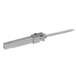
IZD10, Sensore Elettrostatico
[Features]
· Confirming the actual status is important when managing static electricity.
· Can be used for a wide-range of electrostatic potential measurement applications.
· Compact and easy to mount.
· RoHS compliant.
· Installation distance (IZD10-110) 10 to 50 mm (±0.4 kV at an installation distance of 25 mm).
· Installation distance (IZD10-510) 25 to 75 mm (±20 kV at an installation distance of 50 mm).
(i)Nota
- Please refer to the manufacturer's catalog for specification details.
- Product images may be representative images. Refer to the manufacturer's catalog for shape details.
Codice componente
Qui sono indicati i codici componente
correlati al prodotto ricercato
Electrostatic Sensor, IZD10 Series Specifications
| Electrostatic Sensor Type | IZD10-110 | IZD10-510 |
|---|---|---|
| Potential Measurement | ±0.4 kV (detection range at 25 mm)* | ±20 kV (detection range at 50 mm)* |
| Output Voltage | 1 to 5 V (Output impedance: Approx. 100Ω) | |
| Effective Detection Distance | 10 to 50 mm | 25 to 75 mm |
| Linearity | ±5% F.S. (0 to 50°C, at detection distance of 25 mm) | ±5%F.S. (0 to 50°C, at detection distance of 50 mm) |
| Output Delay Time | 100 ms or less | |
| Power Supply Voltage | 21.6 to 26.4 V DC (Within 24 V DC ±10%) | |
| Current Consumption | 40 mA or less | |
| Ambient Operating Temperature | 0 to 50°C | |
| Ambient Humidity | 35 to 85% Rh (with no condensation) | |
| Material | Head case: ABS, Amplifier case: ABS | |
| Vibration Resistance | Durability 50 Hz, Amplitude 1 mm, X, Y, Z: 2 hours each | |
| Impact Resistance | 100 m/s2 | |
| Weight | 185 g (including cable weight) | |
| Compliance with EN Standards | Protective Class: Class III (EN60950-1) Pollution Degree 3 CE Marking: Low voltage directive: 2006/95/EC Only when connected to a SELV-type external circuit | |
| EMC Directive | 2004/108/EC | |
| UL Standard | UL508 | |
*The measured potential and output voltage varies depending on the detection distance. For details of the relationship between measured potentials and output voltages according to detection distance, refer to the "Output Signal" graphs in the Technical Data section of the catalog.
Connection Circuit and Wiring Table
Connect the lead wires according to the connection circuit and wiring table.
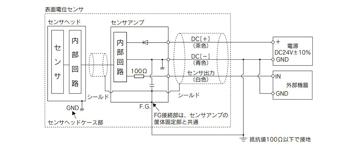
IZD10 Series connection circuit
| Lead Wire Coating Color | Description | Function |
|---|---|---|
| Brown | DC (+) | Power supply 24 V DC |
| Blue | DC (-) | Power Supply 0 V |
| White | Sensor output | Analog output for 1 to 5 V |
- *Ensure grounding. Ensure GND terminal is grounded with a ground resistance of 100Ω or less. Also, a dedicated power supply is recommended for the sensor-driving power supply. Connecting any equipment other than the sensor to this power supply may trigger the malfunctioning or breakdown of the equipment when static electricity is discharged to the sensor head or when noise enters the GND terminal.
*When using the cable on the external equipment connection side after cutting it short, do not connect a shielding wire (since the shielding wire is a common wire with the amplifier case, provide a frame ground on the amplifier case side). - *Text in ( ) refers to the lead wire coating color of the dedicated cable.
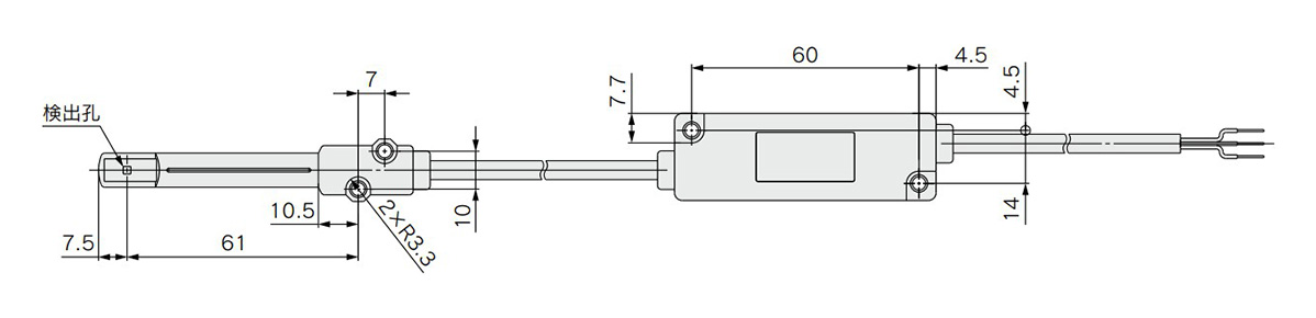
Dimensional Outline Drawing
(Unit: mm)
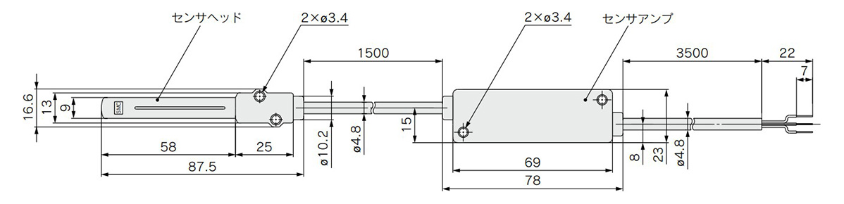
IZD10-110/IZD10-510 dimensional drawing 1
(Unit: mm)
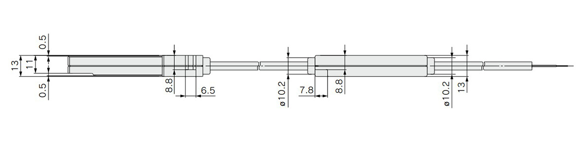
IZD10-110/IZD10-510 dimensional drawing 2
(Unit: mm)
IZD10-110/IZD10-510 dimensional drawing 3
Output Signal
When measuring the potential of a charged object with an electrostatic sensor, the relationship between the electrostatic potential being measured and the output voltage varies depending on the sensor's installation distance. The relationship between the electrostatic sensor's output voltage and the detected electrostatic potential depending on the installation distance is as shown in the figure below. (The installation distance in the figure refers to the distance between the object being measured and the electrostatic sensor.)
Relationship between Sensor Output Voltage and Electrostatic Potential at Each Installation Distance
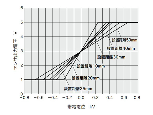
IZD10-110 electrostatic potential graph
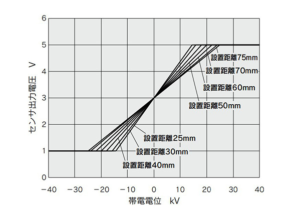
IZD10-510 electrostatic potential graph
Detection Range
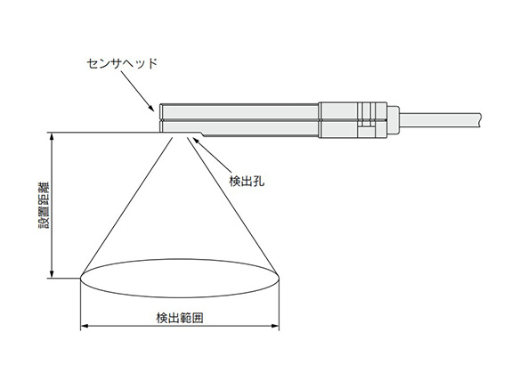
IZD10 Series detection range
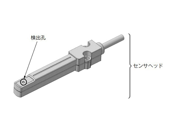
IZD10 Series part names
IZD10-110 (Potential Measurement ±0.4 kV)
| Installation Range (mm) | Detection Range (mm) |
|---|---|
| 10 | 45 |
| 20 | 85 |
| 25 | 100 |
| 30 | 120 |
| 40 | 150 |
| 50 | 180 |
IZD10-510 (Potential Measurement ±20 kV)
| Installation Range (mm) | Detection Range (mm) |
|---|---|
| 25 | 100 |
| 30 | 120 |
| 40 | 150 |
| 50 | 180 |
| 60 | 205 |
| 70 | 225 |
| 75 | 235 |
Specific Product Precautions
- *Product images are representative images. These images may differ from the actual products.
- *Refer to the catalog for further information.
Loading...
Informazioni di base
| Tipo | Dispositivi di misurazione antistatici | Indicatori | Non in dotazione | Funzione aggiuntiva | Non in dotazione |
|---|---|---|---|---|---|
| Funzione di regolazione bilanciamento ioni | Non in dotazione | Alimentazione | 24 V DC |
Configura
Proprietà di base
-
Potenziali misurati
- ±0.4kV (gamma di rilevamento a 25mm)
- ±20kV (gamma di rilevamento a 50mm)
-
Tipo
- IZD10
-
Filtrare per tipo dati CAD
- 2D
- 3D
Filtrare per giorni di spedizione standard
-
- Tutti gli articoli
- 4 giorni o meno
Attributi opzionali
- Specifiche e dimensioni di alcuni componenti potrebbero non essere illustrate in modo esauriente. Per i dettagli esatti, consultare i cataloghi dei produttori .
Supporto tecnico
Metodo di pagamento


Produzione on demand
Certificati


Copyright © MISUMI Corporation All Rights Reserved.