RSH, cilindro stopper, impieghi gravosi

[Features]
· Amount of energy absorption can be adjusted to suit the load.
· Easy replacement of shock absorbers.
· The roller lever direction can be changed in 90° steps.
· Side piping (flange) is possible.
· Bore size 20 mm: Standard stroke 15 mm.
· Bore size 32 mm: Standard stroke 20 mm.
*See the manufacturer's catalog for detailed specifications.
*Product pictures are representations. CAD data is not supported for some model numbers.
(i)Nota
- See catalog for specification details.
- CAD data is not supported for some model numbers
- Product pictures are representations.
Codice componente
Qui sono indicati i codici componente
correlati al prodotto ricercato
Heavy Duty Stopper Cylinder RSH Series Specifications
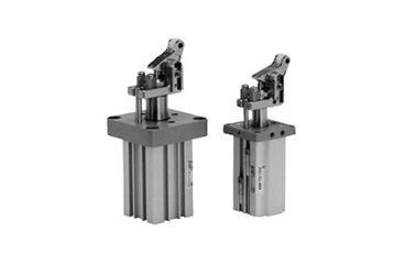
Heavy Duty Stopper Cylinder RSH Series external appearance
| Model | RSH | |
|---|---|---|
| Tube Internal Diameter (mm) | 20 | 32 |
| Operating method | Double acting, Double acting spring type, Single acting (spring extend) | |
| Rod-end configuration | Lever with built-in shock absorber | |
| Applicable fluids | Air | |
| Proof pressure | 1.5 MPa | |
| Maximum operating pressure | 1.0 MPa | |
| Ambient temperature and working fluid temperature | -10°C to 60°C (no freezing) | |
| Lubrication | Not required (non-lube) | |
| Cushioning | Rubber cushion | |
| Stroke length tolerance | +1.4 0 | |
| Mounting | Flange | |
| Port size Rc, NPT, G | M5 ×; 0.8 | 1/8 |
| - | 1/8 | |
| - | 1/8 | |
Weight list
(Increment: kg)
| Operating method | Rod-end configuration | Tube Internal Diameter (mm) | Weight |
|---|---|---|---|
| Double acting / Double acting spring type / Single acting spring extend | Lever with built-in shock absorber | 20 | 0.41 |
| 32 | 0.75 |
ø20 (20‑mm Diameter) / ø32 (32‑mm Diameter) Structural Drawing
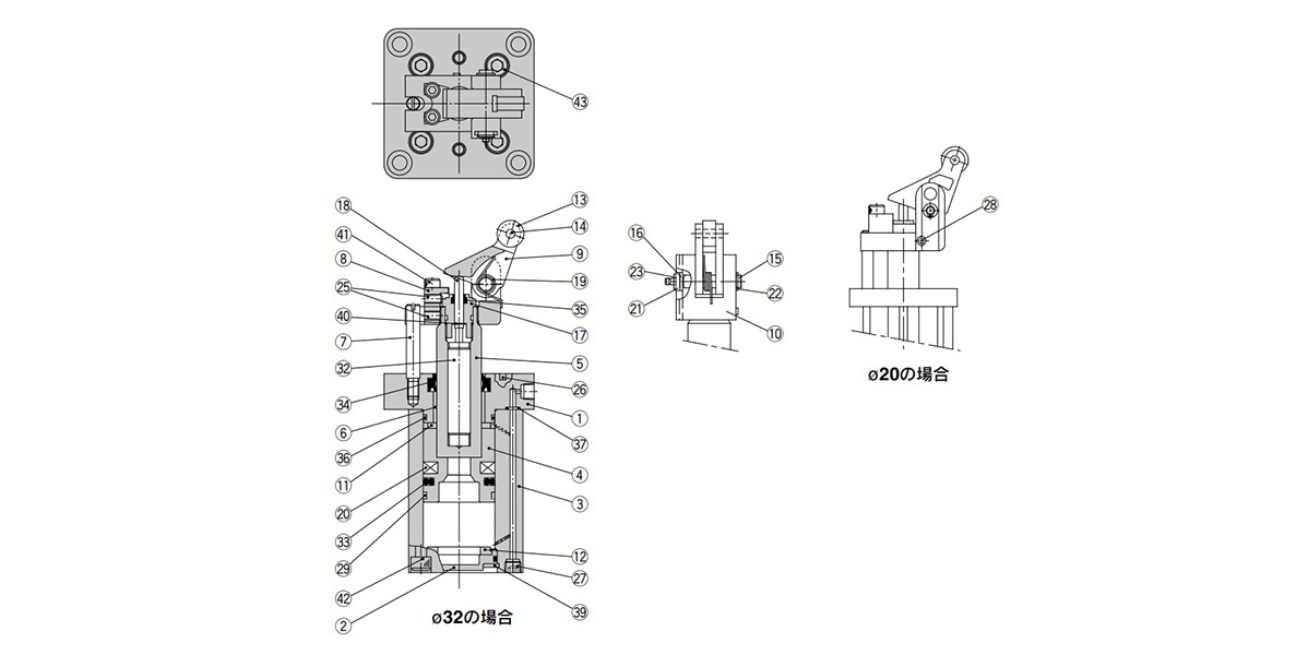
Double acting type (DL, DM) structural drawing
Double acting spring type (BL, BM) structural drawing
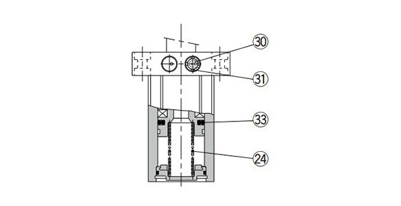
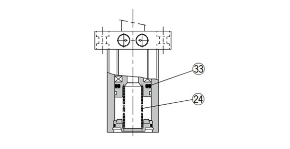
Single acting type (TL, TM)
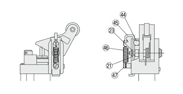
With lock mechanism (-D) structural drawing (option)
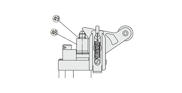
When using cancel cap (-C) structural drawing (option)
Component Parts
| Number | Part name | Material | Note |
|---|---|---|---|
| 1 | Rod Cover | Aluminum Alloy | Metallic painted |
| 2 | Bottom plate | Aluminum Alloy | Chromate |
| 3 | Cylinder tube | Aluminum Alloy | Hard Anodize |
| 4 | Piston | Aluminum Alloy | Chromate |
| 5 | Piston rod | ø20 (20‑mm diameter): Stainless steel ø32 (32‑mm diameter): Carbon steel | Hard chrome plated |
| 6 | Bushing | Resin/Copper alloy (Multiple layers) | - |
| 7 | Guide rod | Carbon steel | Hard chrome plated |
| 8 | Stopper | Stainless steel | - |
| 9 | Lever | Carbon steel | Nickel plating |
| 10 | Lever holder | Carbon steel | Nickel plating |
| 11 | Bumper A | Urethane | - |
| 12 | Bumper B | Urethane | - |
| 13 | Roller | Resin | -□□L |
| Carbon steel | -□□M | ||
| 14 | Spring pin | Carbon tool steel | - |
| 15 | Lever pin | Carbon steel | - |
| 16 | Ring A | Rolled steel | Nickel plating |
| 17 | Adjustment dial | Aluminum Alloy | - |
| 18 | End rod | Special steel | - |
| 19 | Lever spring | Steel wire | - |
| 20 | Magnet | - | - |
| 21 | Flat washer | Steel wire | Nickel plating |
| 22 | C-shaped retaining ring for Shaft | Carbon tool steel | - |
| 23 | Type E retaining ring for shaft | Carbon tool steel | - |
| 24 | Return spring | Steel wire | -T□/-B□ |
| 25 | Hex Socket Set Screw | Chrome Molybdenum Steel | - |
| 26 | Parallel pin | Carbon steel | ø20 (20‑mm diameter) only |
| 27 | Hexagon socket head plug | Chrome Molybdenum Steel | Nickel plating |
| 28 | Spring pin | Carbon tool steel | ø20 (20‑mm diameter) only |
| 29 | Wear ring | Resin | - |
| 30 | Element | Bronze | -T□ only (ø20 [20‑mm diameter] is socket set screw) |
| 31 | Retaining Ring | Carbon tool steel | ø32 (32‑mm diameter) -T□ only |
| 32 | Shock absorber | - | - |
| 33 | Piston Gasket | NBR | - |
| 34 | Rod Gasket | NBR | - |
| 35 | Scraper | NBR | - |
| 36 | Tube gasket | NBR | - |
| 37 | O-ring | NBR | - |
| 38 | Bottom plate gasket | NBR | - |
| 39 | C shape retaining ring for hole | Carbon tool steel | Phosphate coated |
| 40 | Type CE retaining ring for shaft | Carbon tool steel | Phosphate coated |
| 41 | Hexagon socket head bolt | Chrome Molybdenum Steel | Zinc chromate |
| 42 | Hexagon socket head bolt | Stainless steel | ø20 (20‑mm diameter) only |
| 43 | Hexagon socket head bolt | Stainless steel | ø32 (32‑mm diameter) only |
| 44 | Steel ball | Carbon steel | - |
| 45 | Bracket | Carbon steel | Chromate |
| 46 | Bracket spring | Stainless steel wire | - |
| 47 | Pin E | Stainless steel | - |
| 48 | Cancel cap | Aluminum Alloy | Clear anodized |
| 49 | O-ring | NBR | - |
Replacement Parts / Seal Kit
| Bore size (mm) | Kit No. | Content | ||
|---|---|---|---|---|
| Double acting type | Double acting spring type | Single acting | ||
| 20 | RSH20D-PS | RSH20T-PS | Set of items (33) to (37) in above table (excluding [34]) | |
| 32 | RSH32D-PS | RSH32T-PS | ||
- *Seal kit includes (33) to (37) (excluding [34]). Order the seal kit based on each bore size.
- *The seal kit does not include a grease pack, so please order a grease pack separately.
Grease pack part number: GR-S-010 (10 g)
Replacement Parts / Shock Absorber
| Bore size (mm) | Kit No. |
|---|---|
| 20 | RSH-R20 |
| 32 | RSH-R32 |
Outline dimensional drawing
(Unit: mm)
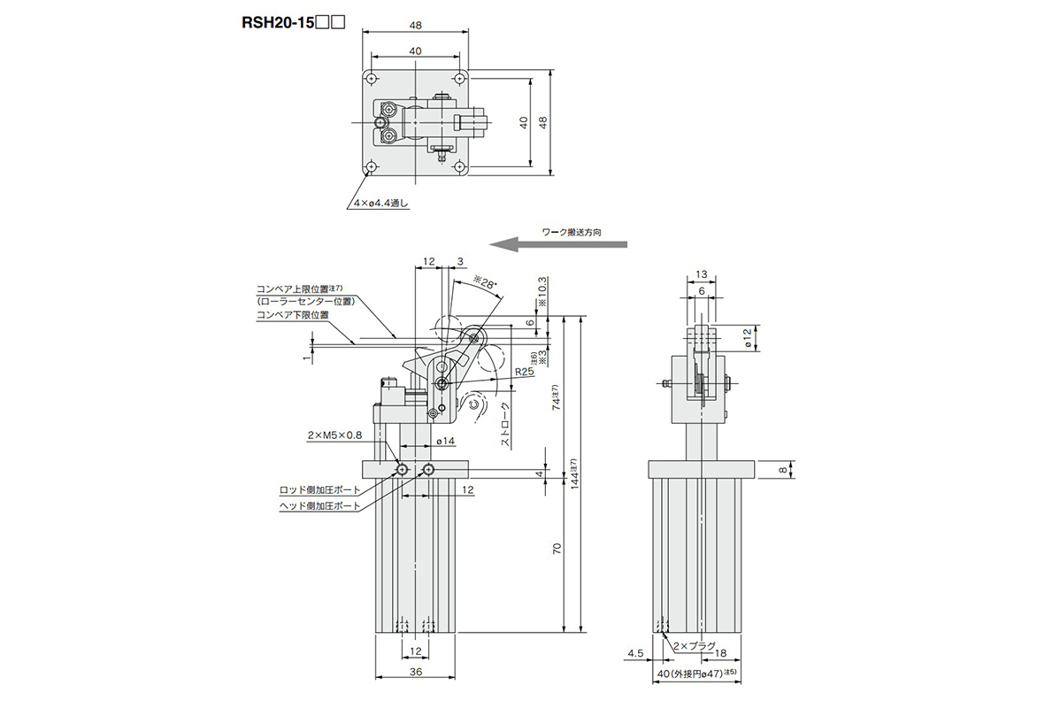
ø20 (20‑mm diameter) dimensional outline drawing
Note 1) The figure shows dimensions at the maximum energy absorption capacity.
Note 2) The dimensional outline drawing for the model with auto switch is identical to the above.
Note 3) The figure shows an extended piston rod.
Note 4) The dimensions marked with * vary according to adjustment of the shock absorber dial.
Note 5) Circumscribed circle ø47 (47‑mm diameter) means the diameter of the circle circumscribed to the cylinder tube angles. The mounting hole diameter must be ø48 (48‑mm diameter). Be careful of the interference between the lever and the mounting base when mounted from the lever side. Thus, the thickness of the mounting base must be 8 mm or less.
Note 6) It is recommended to set the conveyor height in a range from the lower limit position to the upper limit position of the conveyor (dimension *3 shown in the figure).
Note 7) The dimensions in the figure do not include the stroke length tolerance (0 to +1.4 mm). When fixing the cylinder (setting the conveyor position), take this into consideration and be sure to set the cylinder within the range of Note 6, using the upper limit position of the conveyor (roller center position) as a reference.
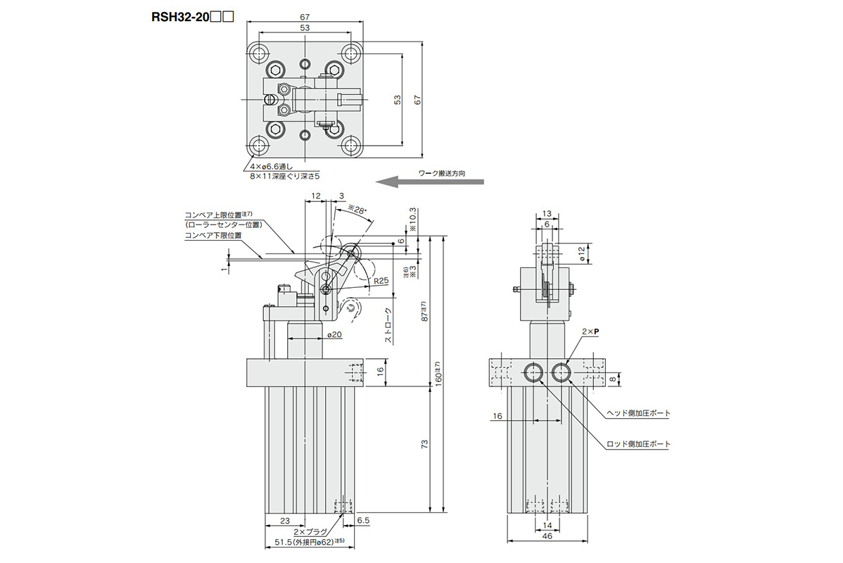
ø32 (32‑mm diameter) dimensional outline drawing
P (piping port)
- Nil: Rc 1/8
- TN: NPT 1/8
- TF: G 1/8
Note 1) The figure shows dimensions at the maximum energy absorption capacity.
Note 2) The dimensional outline drawing for the model with auto switch is identical to the above.
Note 3) The figure shows an extended piston rod.
Note 4) The dimensions marked with * vary according to adjustment of the shock absorber dial.
Note 5) Circumscribed circle ø62 (62‑mm diameter) means the diameter of the circle circumscribed to the cylinder tube angles. The mounting hole diameter must be ø63 (63‑mm diameter). Be careful of the interference between the lever and the mounting base when mounted from the lever side. Thus, the thickness of the mounting base must be 9 mm or less.
Note 6) It is recommended to set the conveyor height in a range from the lower limit position to the upper limit position of the conveyor (dimension *3 shown in the figure).
Note 7) The dimensions in the figure do not include the stroke length tolerance (0 to +1.4 mm). When fixing the cylinder (setting the conveyor position), take this into consideration and be sure to set the cylinder within the range of Note 6, using the upper limit position of the conveyor (roller center position) as a reference.
Operation Precautions
- 1. In case of cylinders with locking mechanism, do not apply an external force from the opposite side when the lever is locked. Lower the cylinder before adjusting the conveyor or moving the pallet.
- 2. In case of cylinders with locking mechanism, do not collide the pallet and roller when the lever is locked. If the pallet collides with the roller in the locked state, it may cause lever malfunction. (The lever is released when the cylinder is fully retracted.)
- 3. Do not let your hand become caught when operating the cylinder. The lever holder goes up and down while the cylinder is in operation. Pay sufficient attention not to let your hand or fingers become caught between the rod cover and lever holder.
- 4. Do not let water, cutting oil or dust splash on the equipment. It can cause oil leakage and malfunction of the shock absorber.
- 5. The stop state of the workpiece may vary depending on changes in ambient temperature or secular changes in shock absorber resistive force. Check the stop state periodically and adjust the shock absorber resistive force at appropriate intervals.
*See the manufacturer's catalog for product information other than the above.
Codice componente
|
|---|
| RSH20-15TM |
| RSH20-15TM-M9PW |
| RSH32-20TM |
| RSH32-20TM-D |
| RSH32-20TM-DCS |
| RSH32TF-20TL |
| RSH32TF-20TL-D |
| RSH32TF-20TL-S |
| RSH32TF-20TM |
| RSH32TF-20TM-D |
| Codice componente |
Prezzo unitario standard
| Quantità minima d'ordine | Sconto volumi elevati | Metodo di funzionamento cilindro | D.I. cilindro: D (Ø) | Corsa: L (mm) | Operating Pressure (MPa) | Port thread type | Body Options | Auto Switch | Lead Wire Length (m) | Number of Switches | Materiale rullo | Tipo di connettore | |
|---|---|---|---|---|---|---|---|---|---|---|---|---|---|---|---|
295.32 € | 1 | 26 giorni | [Ad azione singola (Ritrazione)] Ad azione singola speciale (ritratto da forza esterna) | 20 | - | 1.0 | M | Senza opzione | Senza (magnete incorporato) | - | - | Acciaio al carbonio | - | ||
362.97 € | 1 | 26 giorni | [Ad azione singola (Ritrazione)] Ad azione singola speciale (ritratto da forza esterna) | 20 | - | 1.0 | M | Senza opzione | M9PW | 0.5 | 2 pz. | Acciaio al carbonio | - | ||
307.98 € | 1 | 4 giorni | [Ad azione singola (Ritrazione)] Ad azione singola speciale (ritratto da forza esterna) | 32 | 20 | 1.0 | Rc | Senza opzione | Senza (magnete incorporato) | - | - | Acciaio al carbonio | - | ||
319.81 € | 1 | 26 giorni | [Ad azione singola (Ritrazione)] Ad azione singola speciale (ritratto da forza esterna) | 32 | - | 1.0 | Rc | Con meccanismo di blocco | Senza (magnete incorporato) | - | - | Acciaio al carbonio | - | ||
437.60 € | 1 | 26 giorni | [Ad azione singola (Ritrazione)] Ad azione singola speciale (ritratto da forza esterna) | 32 | - | - | Rc | Con meccanismo di blocco, con cappuccio di annullamento, con interruttore di rilevamento a leva | Senza interruttore automatico (magnete incorporato) | Assente | Assente | Acciaio al carbonio | Assente | ||
307.98 € | 1 | 26 giorni | [Ad azione singola (Ritrazione)] Ad azione singola speciale (ritratto da forza esterna) | 32 | - | 1.0 | G | Senza opzione | Senza (magnete incorporato) | - | - | Resina | - | ||
319.81 € | 1 | 26 giorni | [Ad azione singola (Ritrazione)] Ad azione singola speciale (ritratto da forza esterna) | 32 | - | - | G | Con meccanismo di blocco | Senza interruttore automatico (magnete incorporato) | Assente | Assente | Resina | Assente | ||
419.13 € | 1 | 26 giorni | [Ad azione singola (Ritrazione)] Ad azione singola speciale (ritratto da forza esterna) | 32 | - | 1.0 | G | Con interruttore di rilevamento a leva | Senza (magnete incorporato) | - | - | Resina | - | ||
307.98 € | 1 | 26 giorni | [Ad azione singola (Ritrazione)] Ad azione singola speciale (ritratto da forza esterna) | 32 | - | 1.0 | G | Senza opzione | Senza (magnete incorporato) | - | - | Acciaio al carbonio | - | ||
319.85 € | 1 | 36 giorni | [Ad azione singola (Ritrazione)] Ad azione singola speciale (ritratto da forza esterna) | 32 | - | 1.0 | G | Con meccanismo di blocco | Senza (magnete incorporato) | - | - | Acciaio al carbonio | - |
Loading...
Informazioni di base
| Metodo di funzionamento asta | Aste singole | Profilo corpo principale | Cilindro piatto | Funzione aggiuntiva | Standard |
|---|---|---|---|---|---|
| Ambiente, applicazioni | Standard | Cushion | Smorzatore in gomma | Rod Tip Shape | Leva con ammortizzatore incorporato |
| Tube Material | Lega di alluminio / Alluminio anodizzato rigido | Specification of cylinder | Cilindro di arresto per impieghi pesanti | Mount Type | Flangia |
Configura
Proprietà di base
-
D.I. cilindro: D(Ø)
-
Corsa: L(mm)
-
Operating Pressure(MPa)
- 1.0
-
Port thread type
- G
- M
- Rc
- Vite M
-
Body Options
- Con cappuccio di annullamento
- Con interruttore di rilevamento a leva
- Con meccanismo di blocco
- Con meccanismo di blocco, con cappuccio di annullamento
- Con meccanismo di blocco, con cappuccio di annullamento, con interruttore di rilevamento a leva
- Con meccanismo di blocco, con interruttore di rilevamento a leva
- Senza opzione
-
Auto Switch
-
Lead Wire Length(m)
- 0.5
- 3
- Assente
-
Number of Switches
-
Materiale rullo
- Acciaio al carbonio
- Resina
-
Tipo di connettore
- Assente
-
Tipo
- RSH
- RSH32
-
Metodo di funzionamento cilindro
- A doppia azione
- Ad azione singola (Ritrazione)
- A doppia azione
-
Filtrare per tipo dati CAD
- 2D
- 3D
Filtrare per giorni di spedizione standard
-
- Tutti gli articoli
- 4 giorni o meno
- 26 giorni o meno
- 36 giorni o meno
Attributi opzionali
- Product pictures are representations.
- Specifiche e dimensioni di alcuni componenti potrebbero non essere illustrate in modo esauriente. Per i dettagli esatti, consultare i cataloghi dei produttori .
Supporto tecnico
Metodo di pagamento


Produzione on demand
Certificati


Copyright © MISUMI Corporation All Rights Reserved.