Attuatori Attuatore lineare / elettrico Cursore con trasmissione a cinghia serie LEFB Motore passo-passo / servomotore
[Features]
· Maximum stroke: 2,000 mm (step motor [24‑V DC servo]).
· Maximum speed: 2,000 mm/s (step motor [24‑V DC servo]).
· Positioning repeatability: ±0.08 mm (step motor [24‑V DC servo]).
· Maximum speed: 2,000 mm/s (AC servo motor).
· Maximum stroke: 3,000 mm (AC servo motor).
· Maximum acceleration/deceleration: 20,000 mm/S2 (AC servo motor).
· Pulse input type, with absolute encoder (AC servo motor).
· Positioning Repeatability: ±0.06 mm (AC servo motor).
(i)Nota
- Webpages for products currently without individual pages on this site will be released on an ad-hoc basis.
- Refer to the manufacturer's catalog for specification and material details.
- Product images may be representative images only. Refer to the manufacturer's catalog for shape details.
- CAD data is not available for some model numbers.
Codice componente
Qui sono indicati i codici componente
correlati al prodotto ricercato
Electric Actuator, Slider Type, Belt Drive LEFB Series Specifications

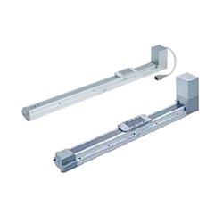
Electric Actuator, Slider Type, Belt Drive LEFB Series external appearance
Specifications / Step Motor (24‑V DC Servo)
| Model | LEFB16 | LEFB25 | LEFB32 | |||
|---|---|---|---|---|---|---|
| Actuator Specifications | Stroke [mm] Note 1: | 300, 500, 600, 700 800, 900, 1,000 | 300, 500, 600, 700, 800, 900 1,000, 1,200, 1,500, 1,800, 2,000 | 300, 500, 600, 700, 800, 900 1,000, 1,200, 1,500, 1,800, 2,000 | ||
| Work Load [kg] Note 2: | Horizontal | LECP6/LECP1/LECPMJ JXCE1/91/P1/D1 | 1 | 10 | 19 | |
| LECPA | 1 | 5 | 14 | |||
| Speed [mm/s] Note 2: | 48 to 1,100 | 48 to 1,400 | 48 to 1,500 | |||
| Maximum Acceleration/Deceleration [mm/s2] | 3,000 | |||||
| Positioning Repeatability [mm] | ±0.08 | |||||
| Lost Motion [mm] Note 3: | 0.1 or less | |||||
| Lead [mm] | 48 | 48 | 48 | |||
| Impact/Vibration Resistance [m/s2] Note 4: | 50/20 | |||||
| Actuation Type | Belt | |||||
| Guide Type | Linear guide | |||||
| Operating Temperature Range [°C] | 5 to 40 | |||||
| Operating Humidity Range [%RH] | 90 or less (no condensation) | |||||
| Electrical Specifications | Motor Size | □28 | □42 | □56.4 | ||
| Motor type | Step motor (24‑V DC servo) | |||||
| Encoder | Incremental A/B phase (800 pulses/rotation) | |||||
| Rated Voltage [V] | 24 DC ±10% | |||||
| Power Consumption [W] Note 5: | 24 | 32 | 52 | |||
| Standby Power Consumption When Operating [W] Note 6: | 18 | 16 | 44 | |||
| Maximum Instantaneous Power Consumption [W] Note 7: | 51 | 60 | 127 | |||
| Lock Specifications | Type Note 8: | Non-excitation operation (non-magnetizing lock) | ||||
| Holding Force [N] | 4 | 19 | 36 | |||
| Power Consumption [W] Note 9: | 2.9 | 5 | 5 | |||
| Rated Voltage [V] | 24 DC ±10% | |||||
Note 1: Non-standard strokes are manufactured as custom orders.
Note 2: The speed changes according to the controller/driver type and work load. See p. 41 of the SMC catalog ("Speed−Work Load Graph (Guide)") for more details. Furthermore, if the cable length exceeds 5 m, then it will decrease by up to 10% for each 5 m. Cannot be used vertically.
Note 3: A reference value for correcting an error in reciprocal operation.
Note 4: Impact resistance: No malfunction occurred when the actuator was tested with a drop tester in both an axial direction and a perpendicular direction to the lead screw. (Test was performed with the actuator in the initial state.)
Vibration resistance: No malfunction occurred in a test ranging between 45 and 2,000 Hz (1 sweep), performed in both an axial direction and a perpendicular direction to the lead screw. (Test was performed with the actuator in the initial state.)
Note 5: The power consumption (including the controller) is for when the actuator is operating.
Note 6: The standby power consumption when operating (including the controller) is for when the actuator is stopped in the set position during operation.
Note 7: The maximum instantaneous power consumption (including the controller) is for when the actuator is operating. This value can be used for selecting the power supply capacity.
Note 8: With lock only.
Note 9: For an actuator with a lock, add the power consumption for the lock.
Specifications / Servo Motor (24 V DC)
| Model | LEFB16A | LEFB25A | ||
|---|---|---|---|---|
| Actuator Specifications | Stroke [mm] Note 1: | 300, 500, 600, 700 800, 900, 1,000 | 300, 500, 600, 700, 800, 900 1,000, 1,200, 1,500, 1,800, 2,000 | |
| Work Load [kg] Note 2: | Horizontal | 1 | 2 | |
| Speed [mm/s] Note 2: | 5 to 2,000 | 5 to 2,000 | ||
| Maximum Acceleration/Deceleration [mm/s2] | 3,000 | |||
| Positioning Repeatability [mm] | ±0.08 | |||
| Lost Motion [mm] Note 3: | 0.1 or less | |||
| Lead [mm] | 48 | 48 | ||
| Impact/Vibration Resistance [m/s2] Note 4: | 50/20 | |||
| Actuation Type | Belt | |||
| Guide Type | Linear guide | |||
| Operating Temperature Range [°C] | 5 to 40 | |||
| Operating Humidity Range [%RH] | 90 or less (no condensation) | |||
| Electrical Specifications | Motor Size | □28 | □42 | |
| Motor Output [W] | 30 | 36 | ||
| Motor type | Servo motor (24 V DC) | |||
| Encoder | Incremental A/B (800 pulses/rotation) / Z phase | |||
| Rated Voltage [V] | 24 DC ±10% | |||
| Power Consumption [W] Note 5: | 78 | 69 | ||
| Standby Power Consumption When Operating [W] Note 6: | Horizontal 4 | Horizontal 5 | ||
| Maximum Instantaneous Power Consumption [W] Note 7: | 87 | 120 | ||
| Lock Specifications | Type Note 8: | Non-excitation operation (non-magnetizing lock) | ||
| Holding Force [N] | 4 | 19 | ||
| Power Consumption [W] Note 9: | 2.9 | 5 | ||
| Rated Voltage [V] | 24 DC ±10% | |||
Note 1: Non-standard strokes are manufactured as custom orders.
Note 2: See p. 42 of the SMC catalog ("Speed−Work Load Graph (Guide)") for more details. Furthermore, if the cable length exceeds 5 m, then it will decrease by up to 10% for each 5 m.
Note 3: A reference value for correcting an error in reciprocal operation.
Note 4: Impact resistance: No malfunction occurred when the actuator was tested with a drop tester in both an axial direction and a perpendicular direction to the lead screw. (Test was performed with the actuator in the initial state.)
Vibration resistance: No malfunction occurred in a test ranging between 45 and 2,000 Hz (1 sweep), performed in both an axial direction and a perpendicular direction to the lead screw. (Test was performed with the actuator in the initial state.)
Note 5: The power consumption (including the controller) is for when the actuator is operating.
Note 6: The standby power consumption when operating (including the controller) is for when the actuator is stopped in the set position while operating with maximum load.
Note 7: The maximum instantaneous power consumption (including the controller) is for when the actuator is operating. This value can be used for selecting the power supply capacity.
Note 8: With lock only.
Note 9: For an actuator with a lock, add the power consumption for the lock.
Dimensions / Belt Drive
(Units: mm)
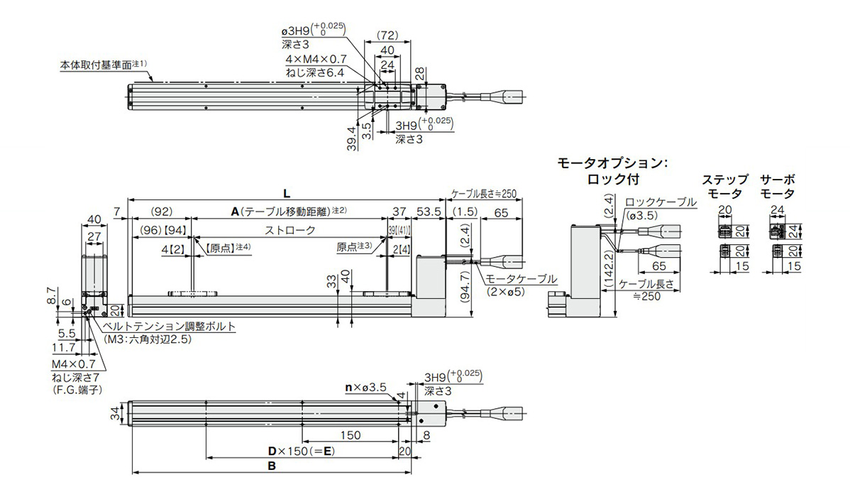
LEFB16 dimensional drawing
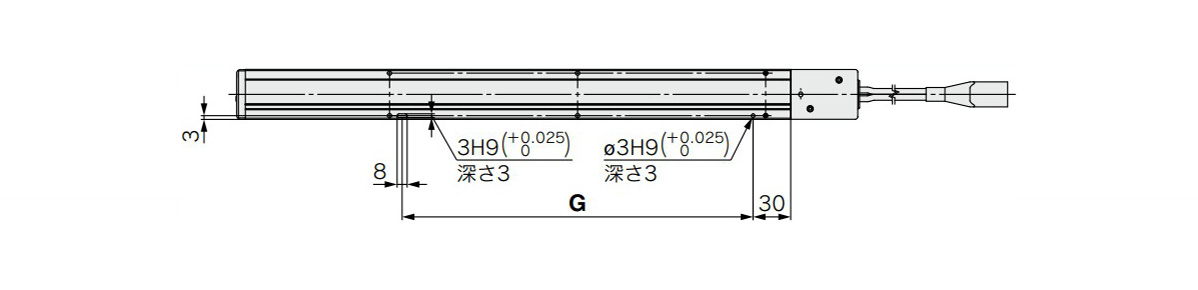
LEFB16 positioning pin hole (Note 5) (Optional): Body bottom surface dimensions
- LEFB16□T-300□/L: 495.5 mm, A: 306 mm, B: 435 mm, n: 6 mm, D: 2 mm, E: 300 mm, G: 280 mm
- LEFB16□T-500□/L: 695.5 mm, A: 506 mm, B: 635 mm, n: 10 mm, D: 4 mm, E: 600 mm, G: 580 mm
- LEFB16□T-600□/L: 795.5 mm, A: 606 mm, B: 735 mm, n: 10 mm, D: 4 mm, E: 600 mm, G: 580 mm
- LEFB16□T-700□/L: 895.5 mm, A: 706 mm, B: 835 mm, n: 12 mm, D: 5 mm, E: 750 mm, G: 730 mm
- LEFB16□T-800□/L: 995.5 mm, A: 806 mm, B: 935 mm, n: 14 mm, D: 6 mm, E: 900 mm, G: 880 mm
- LEFB16□T-900□/L: 1,095.5 mm, A: 906 mm, B: 1,035 mm, n: 14 mm, D: 6 mm, E: 900 mm, G: 880 mm
- LEFB16□T-1000□/L: 1,195.5 mm, A: 1,006 mm, B: 1,135 mm, n: 16 mm, D: 7 mm, E: 1,050 mm, G: 1,030 mm
Note 1: Because of the rounded chamfering, when mounting the actuator using the body mounting reference plane, set the height of the opposite surface or pin to be at least 2 mm or more. (Recommended height: 5 mm)
Note 2: Distance within which the table can move when it returns to origin, etc. Make sure any workpiece mounted on the table does not interfere with the workpieces and equipment, etc., around the table.
Note 3: Position after return to origin.
Note 4: Values within [ ] are for when the direction of return to origin has been changed.
Note 5: When using the body bottom positioning pin holes, do not use the housing B bottom pin hole.
Diagram
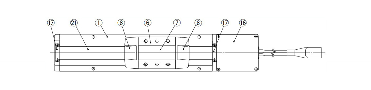
LEFB Series diagram 1
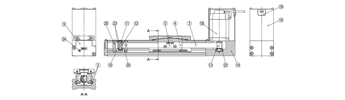
LEFB Series diagram 2
| Number | Part Name | Material | Note |
|---|---|---|---|
| 1 | Body | Aluminum alloy | Anodized |
| 2 | Rail Guide | - | - |
| 3 | Belt | - | - |
| 4 | Belt Holder | Carbon steel | Chromated |
| 5 | Belt Stopper | Aluminum alloy | Anodized |
| 6 | Table | Aluminum alloy | Anodized |
| 7 | Blanking Plate | Aluminum alloy | Anodized |
| 8 | Seal Band Holder | Synthetic resin | - |
| 9 | Housing A | Aluminum diecast | Coating |
| 10 | Pulley Holder | Aluminum alloy | - |
| 11 | Pulley Shaft | Stainless steel | - |
| 12 | End Pulley | Aluminum alloy | Anodized |
| 13 | Motor Pulley | Aluminum alloy | Anodized |
| 14 | Motor Mount | Aluminum alloy | Anodized |
| 15 | Motor Cover | Aluminum alloy | Anodized |
| 16 | End Cover | Aluminum alloy | Anodized |
| 17 | Band Stopper | Stainless steel | - |
| 18 | Motor | - | - |
| 19 | Rubber Bushing | NBR | - |
| 20 | Stopper | Aluminum alloy | - |
| 21 | Dust Seal Band | Stainless steel | - |
| 22 | Bearing | - | - |
| 23 | Bearing | - | - |
| 24 | Tension Adjustment Cap Screw | Chrome molybdenum steel | Chromated |
| 25 | Pulley Retaining Screw | Chrome molybdenum steel | Chromated |
Notes
- *Do not apply load in excess of the specification limits. Select a suitable actuator by work load and allowable moment. If the product is used outside of the specification limits, the unbalanced load applied to the guide will be excessive and have adverse effects, such as creating play on the guide, degrading accuracy and shortening the lifespan of the product.
- *Do not use the product in applications where excessive external force or impact force is applied to it. Doing so can cause the product to malfunction.
- *Refer to the SMC catalog for product information other than what is detailed above.
- *The product image is a representative image only.
| Codice componente |
Prezzo unitario standard
| Quantità minima d'ordine | Sconto volumi elevati | Stroke (mm) | Max. Transportable Mass Range (Horizontal) (kg) | Max. Transportable Mass (Horizontal) (kg) | Lead (mm) | I/O Module | Table Width W1 (mm) | Brake | Table Length L1 (mm) | Maximum Velocity (mm/sec) | Misura | Tipo motore | Opzioni motore | Tipo attuatore / cavo | Lunghezza cavo attuatore (m) | Tipo controller / driver | Lunghezza cavo I/O / spina per comunicazioni (m) | Metodi di montaggio controller / driver | Applicazione di grasso (parte fascia di tenuta) | Staffa di montaggio interruttore automatico | Foro perno di posizionamento | |
|---|---|---|---|---|---|---|---|---|---|---|---|---|---|---|---|---|---|---|---|---|---|---|---|---|
1,744.39 € | 1 | 26 giorni | 1,000 | 2.1–5.0 | 5 | 48 | PNP | 50 | Non in dotazione | 102 | 3,000 | 25 | Motore passo-passo (servo 24-V DC) | Senza blocco | Cavo robotico (cavo resistente alla flessione) | 3 | LECPA (tipo di ingresso a Legumi) | 3 | Montaggio a vite | - | - | - | ||
1,835.31 € | 1 | 26 giorni | 1,000 | 2.1–5.0 | 5 | Equivalente a 48 | PNP | 50 | Non in dotazione | 102 | 1400 | 25 | Motore passo-passo (servo 24-V DC) | Senza blocco | Cavo robotico (cavo resistente alla flessione) | 5 | LECPA (tipo di ingresso a Legumi) | 1.5 | Tipo montaggio su guida DIN | Sì | Nessuno | Fondo dell’alloggio B | ||
1,668.16 € | 1 | 26 giorni | 1,000 | 2.1–5.0 | 5 | 48 | PNP | 50 | Non in dotazione | 102 | 3,000 | 25 | Motore passo-passo (servo 24-V DC) | Senza blocco | Cavo standard | 3 | LECPA (tipo di ingresso a Legumi) | 1.5 | Montaggio a vite | - | - | - | ||
1,820.09 € | 1 | 26 giorni | 1,000 | 2.1–5.0 | 5 | 48 | PNP | 50 | Non in dotazione | 102 | 3,000 | 25 | Motore passo-passo (servo 24-V DC) | With lock | Without cable | Without cable | LECPA (tipo di ingresso a Legumi) | Senza cavo (senza connettore di comunicazione) | Tipo montaggio su guida DIN | - | - | - | ||
1,695.23 € | 1 | 26 giorni | 1,200 | 2.1–5.0 | 5 | 48 | PNP | 50 | Non in dotazione | 102 | 3,000 | 25 | Motore passo-passo (servo 24-V DC) | Senza blocco | Cavo standard | 3 | LECPA (tipo di ingresso a Legumi) | 1.5 | Montaggio a vite | - | - | - | ||
1,829.01 € | 1 | 26 giorni | 1,500 | 2.1–5.0 | 5 | 48 | NPN | 50 | Non in dotazione | 102 | 3,000 | 25 | Motore passo-passo (servo 24-V DC) | Senza blocco | Cavo robotico (cavo resistente alla flessione) | 5 | LECPA (tipo di ingresso a Legumi) | Senza cavo (senza connettore di comunicazione) | Montaggio a vite | - | - | - | ||
1,850.89 € | 1 | 26 giorni | 1,800 | 2.1–5.0 | 5 | 48 | PNP | 50 | Non in dotazione | 102 | 3,000 | 25 | Motore passo-passo (servo 24-V DC) | Senza blocco | Cavo robotico (cavo resistente alla flessione) | 3 | LECPA (tipo di ingresso a Legumi) | 1.5 | Tipo montaggio su guida DIN | - | - | - | ||
1,848.73 € | 1 | 26 giorni | 1,800 | 2.1–5.0 | 5 | Equivalente a 48 | PNP | 50 | Non in dotazione | 102 | 1400 | 25 | Motore passo-passo (servo 24-V DC) | Senza blocco | Cavo standard | 5 | LECPA (tipo di ingresso a Legumi) | 1.5 | Tipo montaggio su guida DIN | Sì | Nessuno | Fondo dell’alloggio B | ||
1,833.77 € | 1 | 26 giorni | 2,000 | 2.1–5.0 | 5 | 48 | NPN | 50 | Non in dotazione | 102 | 3,000 | 25 | Motore passo-passo (servo 24-V DC) | Senza blocco | Cavo standard | 3 | LECPA (tipo di ingresso a Legumi) | 3 | Montaggio a vite | - | - | - | ||
1,389.80 € | 1 | 26 giorni | 300 | 2.1–5.0 | 5 | 48 | PNP | 50 | Non in dotazione | 102 | 3,000 | 25 | Motore passo-passo (servo 24-V DC) | Senza blocco | Cavo robotico (cavo resistente alla flessione) | 3 | LECPA (tipo di ingresso a Legumi) | 1.5 | Montaggio a vite | - | - | - | ||
1,324.63 € | 1 | 26 giorni | 300 | 2.1–5.0 | 5 | 48 | NPN | 50 | Non in dotazione | 102 | 3,000 | 25 | Motore passo-passo (servo 24-V DC) | Senza blocco | Cavo standard | 1.5 | LECPA (tipo di ingresso a Legumi) | 1.5 | Montaggio a vite | - | - | - | ||
1,338.07 € | 1 | 26 giorni | 300 | 2.1–5.0 | 5 | 48 | PNP | 50 | Non in dotazione | 102 | 3,000 | 25 | Motore passo-passo (servo 24-V DC) | Senza blocco | Cavo standard | 3 | LECPA (tipo di ingresso a Legumi) | 1.5 | Montaggio a vite | - | - | - | ||
1,412.13 € | 1 | 26 giorni | 300 | 2.1–5.0 | 5 | Equivalente a 48 | PNP | 50 | Non in dotazione | 102 | 1400 | 25 | Motore passo-passo (servo 24-V DC) | Senza blocco | Cavo standard | 5 | LECPA (tipo di ingresso a Legumi) | 3 | Montaggio a vite | Sì | Nessuno | Fondo dell’alloggio B | ||
1,419.70 € | 1 | 26 giorni | 500 | 2.1–5.0 | 5 | 48 | PNP | 50 | Non in dotazione | 102 | 3,000 | 25 | Motore passo-passo (servo 24-V DC) | Senza blocco | Cavo robotico (cavo resistente alla flessione) | 1.5 | LECPA (tipo di ingresso a Legumi) | 1.5 | Montaggio a vite | - | - | - | ||
1,455.79 € | 1 | 26 giorni | 500 | 2.1–5.0 | 5 | 48 | PNP | 50 | Non in dotazione | 102 | 3,000 | 25 | Motore passo-passo (servo 24-V DC) | Senza blocco | Cavo robotico (cavo resistente alla flessione) | 3 | LECPA (tipo di ingresso a Legumi) | 1.5 | Montaggio a vite | - | - | - | ||
1,506.24 € | 1 | 26 giorni | 500 | 2.1–5.0 | 5 | 48 | PNP | 50 | Non in dotazione | 102 | 3,000 | 25 | Motore passo-passo (servo 24-V DC) | Senza blocco | Cavo robotico (cavo resistente alla flessione) | 3 | LECPA (tipo di ingresso a Legumi) | 3 | Tipo montaggio su guida DIN | - | - | - | ||
1,545.27 € | 1 | 26 giorni | 500 | 2.1–5.0 | 5 | 48 | PNP | 50 | Non in dotazione | 102 | 3,000 | 25 | Motore passo-passo (servo 24-V DC) | Senza blocco | Cavo robotico (cavo resistente alla flessione) | 5 | LECPA (tipo di ingresso a Legumi) | 1.5 | Montaggio a vite | - | - | - | ||
1,479.56 € | 1 | 26 giorni | 500 | 2.1–5.0 | 5 | Equivalente a 48 | PNP | 50 | Non in dotazione | 102 | 1400 | 25 | Motore passo-passo (servo 24-V DC) | Senza blocco | Cavo standard | 5 | LECPA (tipo di ingresso a Legumi) | 1.5 | Tipo montaggio su guida DIN | Sì | Nessuno | Fondo dell’alloggio B | ||
1,513.26 € | 1 | 26 giorni | 500 | 2.1–5.0 | 5 | Equivalente a 48 | PNP | 50 | Non in dotazione | 102 | 1400 | 25 | Motore passo-passo (servo 24-V DC) | Senza blocco | Cavo standard | 5 | LECPA (tipo di ingresso a Legumi) | 5 | Tipo montaggio su guida DIN | Sì | Nessuno | Fondo dell’alloggio B | ||
1,619.24 € | 1 | 26 giorni | 600 | 2.1–5.0 | 5 | 48 | PNP | 50 | Non in dotazione | 102 | 3,000 | 25 | Motore passo-passo (servo 24-V DC) | Senza blocco | Cavo robotico (cavo resistente alla flessione) | 5 | LECPA (tipo di ingresso a Legumi) | 1.5 | Tipo montaggio su guida DIN | - | - | - | ||
1,478.04 € | 1 | 26 giorni | 600 | 2.1–5.0 | 5 | 48 | PNP | 50 | Non in dotazione | 102 | 3,000 | 25 | Motore passo-passo (servo 24-V DC) | Senza blocco | Cavo standard | 3 | LECPA (tipo di ingresso a Legumi) | 1.5 | Tipo montaggio su guida DIN | - | - | - | ||
1,631.23 € | 1 | 26 giorni | 700 | 2.1–5.0 | 5 | Equivalente a 48 | PNP | 50 | Non in dotazione | 102 | 1400 | 25 | Motore passo-passo (servo 24-V DC) | Senza blocco | Cavo robotico (cavo resistente alla flessione) | 5 | LECPA (tipo di ingresso a Legumi) | 1.5 | Tipo montaggio su guida DIN | Sì | Nessuno | Fondo dell’alloggio B | ||
1,530.81 € | 1 | 26 giorni | 800 | 2.1–5.0 | 5 | 48 | PNP | 50 | Non in dotazione | 102 | 3,000 | 25 | Motore passo-passo (servo 24-V DC) | Senza blocco | Cavo robotico (cavo resistente alla flessione) | 3 | LECPA (tipo di ingresso a Legumi) | 1.5 | Montaggio a vite | - | - | - | ||
1,829.60 € | 1 | 26 giorni | 800 | 2.1–5.0 | 5 | 48 | PNP | 50 | Non in dotazione | 102 | 3,000 | 25 | Motore passo-passo (servo 24-V DC) | Senza blocco | Cavo robotico (cavo resistente alla flessione) | 10 | LECPA (tipo di ingresso a Legumi) | 1.5 | Tipo montaggio su guida DIN | - | - | - |
Loading...
Informazioni di base
| Main Body, Peripheral Components | Corpo principale | Type | Cursori | Drive Method | Cinghie |
|---|---|---|---|---|---|
| Guide | In dotazione | Input Power Supply | 24 V DC | Position Detection | Incrementale |
| Noise Filters | Non in dotazione | Ambiente d'esercizio | Standard | Positioning Repeatability(µm) | ±80 |
Configura
Proprietà di base
-
Stroke(mm)
-
Max. Transportable Mass (Horizontal)(kg)
-
Lead(mm)
-
I/O Module
- NPN
- PNP
- DeviceNet
- Ethernet
- Non in dotazione
- EtherCAT
- IO-Link
- PROFINET
-
Table Width W1(mm)
-
Brake
- Non in dotazione
- In dotazione
-
Table Length L1(mm)
-
Maximum Velocity(mm/sec)
-
Misura
- 16
- 25
- 32
-
Tipo motore
- Motore passo-passo (servo 24-V DC)
- Servomotore (24 V DC)
-
Opzioni motore
- Senza blocco
- With lock
-
Tipo attuatore / cavo
-
Lunghezza cavo attuatore(m)
- 1.5
- 3
- 5
- 8
- 10
- 15
- 20
- Without cable
-
Tipo controller / driver
- JXCD1 (DeviceNet (TM) ingresso diretto)
- JXCE1 (ingresso diretto EtherCAT)
- JXCL1 (tipo di ingresso diretto IO-link)
- JXCP1 (ingresso diretto PROFINET)
- LECP1 (tipo senza programma)
- LECA6 (tipo di ingresso dati passo)
- LECP6 / LECA6 (tipo di ingresso dati passo)
- LECP6/LECA6, PNP, step data input type
- JXC91 (Ingresso diretto Ethernet/IP)
- LECPA (tipo di ingresso a Legumi)
- Nessuno
-
Lunghezza cavo I/O / spina per comunicazioni(m)
-
Metodi di montaggio controller / driver
- Montaggio a vite
- Tipo montaggio su guida DIN
-
Applicazione di grasso (parte fascia di tenuta)
- Assente (Specifiche dei cilindro/rullo)
- Sì
-
Staffa di montaggio interruttore automatico
- 1 pz incluso (Includere)
- Nessuno
-
Foro perno di posizionamento
- Fondo dell’alloggio B
-
Tipo
- LEFB
-
Max. Transportable Mass Range (Horizontal)(kg)
- 0–2.0
- 2.1–5.0
- 5.1–10.0
- 10,1 - 20,0
-
Filtrare per tipo dati CAD
- 2D
- 3D
Filtrare per giorni di spedizione standard
-
- Tutti gli articoli
- 4 giorni o meno
- 21 giorni o meno
- 26 giorni o meno
Attributi opzionali
- CAD data is not available for some model numbers.
- Specifiche e dimensioni di alcuni componenti potrebbero non essere illustrate in modo esauriente. Per i dettagli esatti, consultare i cataloghi dei produttori .
Supporto tecnico
Metodo di pagamento


Produzione on demand
Certificati


Copyright © MISUMI Corporation All Rights Reserved.