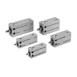
C(D)U-A, cilindro montaggio universale con ammortizzo pneumatico (CDU20-50A-M9N)
Dettagli del prodotto:
Codice articolo del costruttore: CDU20-50A-M9N
Marca: SMC
Prezzo: 179.74 €
Tempi di consegna: 26 giorni
Dati Tecnici:
D.I. cilindro: D: 20 Ø
Corsa: L: - mm
Temperatura di esercizio: - ℃
Pressione di esercizio: 0.08~ 0.7 MPa
Port thread type: M5 × 0.8
(i)Nota
- ■ SMC Product Line
Webpages for products currently without individual pages on this site will be released on an ad-hoc basis. - Refer to the manufacturer's catalog for specification and material details.
- Product images may be representative images. Refer to the manufacturer's catalog for shape details.
Codice componente
Qui sono indicati i codici componente
correlati al prodotto ricercato
CDU20-50A-M9N
CU Series Free Mount Cylinder With Air Cushion
| Model | Pneumatic (non-lube) type |
|---|---|
| Fluid | Air |
| Proof Pressure | 1.0 MPa |
| Maximum operating pressure | 0.7 MPa |
| Minimum operating pressure | 0.08 MPa |
| Ambient and Fluid Temperature | Without auto switch: -10°C to +70 ℃ (no freezing) |
| With auto switch: -10°C to +60 ℃ (no freezing) | |
| Rod-end thread | Male thread |
| Stroke Length Tolerance | 0 to +1.0 |
| Operating piston speed | 50 to 500 mm/s |
Effective Cushion Length
- Bore size 20 mm: effective cushion length 6.6 mm
- Bore size 25 mm: effective cushion length 6.7 mm
- Bore size 32 mm: effective cushion length 7.7 mm
Standard Stroke Table
Bore size 20 mm, 25 mm, 32 mm: standard stroke 20 mm, 30 mm, 40 mm, 50 mm, 60 mm, 70 mm, 80 mm, 90 mm, 100 mm
Diagram
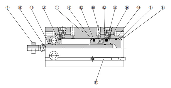
Diagram: CU Series
| Number | Part Name | Material | Quantity | Notes |
|---|---|---|---|---|
| 1 | Cylinder Tube | Aluminum alloy | 1 | Hard anodized aluminum |
| 2 | Rod cover | Aluminum alloy | 1 | Hard anodized aluminum |
| 3 | Head cover | Aluminum alloy | 1 | Chromate |
| 4 | Piston | Aluminum alloy | 1 | Chromate |
| 5 | Piston rod | Stainless steel | 1 | - |
| 6 | Retaining Ring | Carbon tool steel | 1 | Phosphate conversion coating |
| 7 | Rod end nut | Carbon steel | 1 | Chromate |
| 8 | Cushion needle assembly | - | (2) | - |
| 9 | Steel ball | Carbon steel | 2 | - |
| 10 | Magnet | - | 1 | - |
| 11 | Auto switch | - | (2) | - |
| 12 | Piston gasket | NBR | 1 | - |
| 13 | Piston packing | NBR | 2 | - |
| 14 | Rod packing | NBR | 1 | - |
| 15 | Gasket | NBR | 1 | - |
Drawing
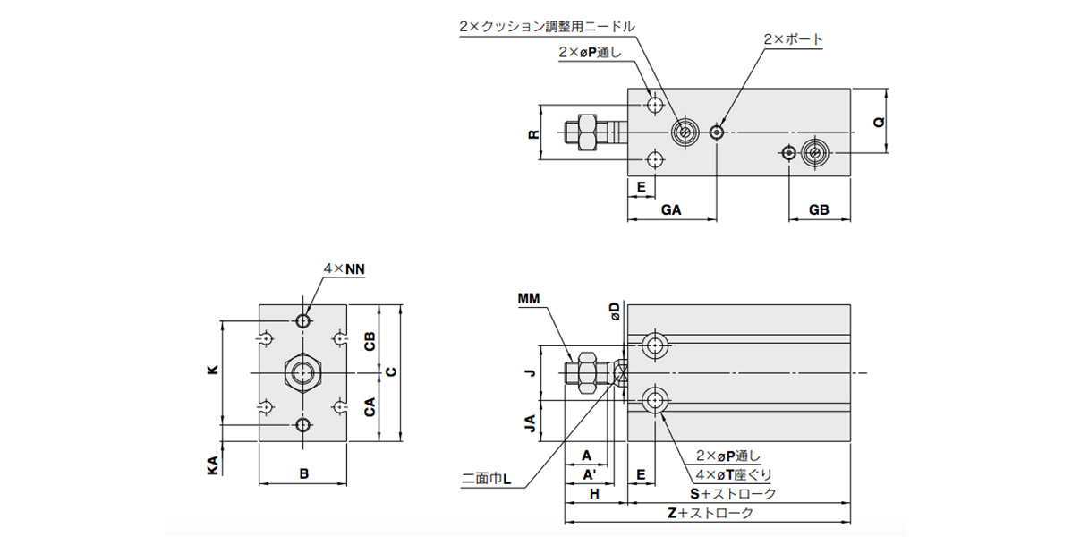
Dimensional drawings: CU Series Free Mount Cylinder With Air Cushion
(Units: mm)
| Tube inner diameter (mm) | Port | A | A' | B | C | CA | CB | D | E | GA | GB | H | J | JA |
|---|---|---|---|---|---|---|---|---|---|---|---|---|---|---|
| 20 | M5 ×; 0.8 | 12 | 14 | 26 | 42 | 20 | 22 | 8 | 9 | 29 | 27 | 19 | 16 | 12 |
| 25 | M5 ×; 0.8 | 15.5 | 18 | 32 | 50 | 25 | 25 | 10 | 10 | 32.5 | 22.5 | 23 | 20 | 15 |
| 32 | 1/8 | 19.5 | 22 | 40 | 62 | 31 | 31 | 12 | 11 | 35 | 25 | 27 | 24 | 19 |
(Units: mm)
| Tube inner diameter (mm) | K | KA | L | MM | NN | P | Q | R | T | S | Z | Standard Stroke |
|---|---|---|---|---|---|---|---|---|---|---|---|---|
| 20 | 30 | 5 | 6 | M6 ×; 1.0 | M5 ×; 0.8 depth 8 | 5.5 | 13 | 16 | 9.3 depth 8 | 53 | 72 | 20, 30, 40, 50, 60, 70, 80, 90, 100 |
| 25 | 38 | 6 | 8 | M8 ×; 1.25 | M5 ×; 0.8 depth 8 | 5.5 | 23.5 | 20 | 9.3 depth 9 | 51.5 | 74.5 | |
| 32 | 48 | 7 | 10 | M10 ×; 1.25 | M6 ×; 1.0 depth 9 | 6.6 | 29 | 24 | 11 depth 11.5 | 56 | 83 |
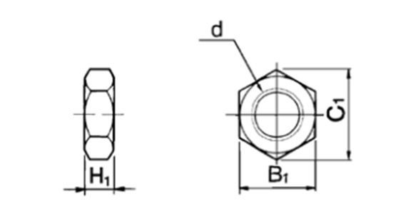
Dimensional drawings: rod-end nut / accessory
(Units: mm)
| Part No. | Applicable Tube Bore Size (mm) | d | H1 | B1 | C1 |
|---|---|---|---|---|---|
| NT-015A | 20 | M6 ×; 1.0 | 5 | 10 | 11.5 |
| NT-02 | 25 | M8 ×; 1.25 | 5 | 13 | 15.0 |
| NT-03 | 32 | M10 ×; 1.25 | 6 | 17 | 19.6 |
Material: carbon steel
Proper Auto Switch Mounting Position (Detection at Stroke End) and Mounting Height
(Units: mm)
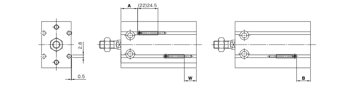
Dimensional drawings: D-A9□/D-M9□/D-M9□W/D-M9□A
*( ): denotes the values of D-A96.
(Units: mm)
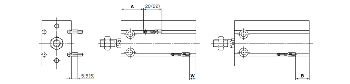
Dimensional drawings: D-A9□V/D-M9□V/D-M9□WV/D-M9□AV
*( ): denotes the values of D-M9□V/D-M9□WV.
(Units: mm)
| Tube inner diameter (mm) | D-A9□, D-A9□V | D-M9□, D-M9□W | D-M9□V, D-M9□WV | D-M9□A | D-M9□AV | ||||||||||
|---|---|---|---|---|---|---|---|---|---|---|---|---|---|---|---|
| A | B | W | A | B | W | A | B | W | A | B | W | A | B | W | |
| 20 | 18 | 15 | 13 (10.5) | 22 | 19 | 9 | 22 | 19 | 11 | 22 | 19 | 11 | 22 | 19 | 13 |
| 25 | 20 | 11 | 9 (6.5) | 24.5 | 15 | 5 | 24.5 | 15 | 7 | 24.5 | 15 | 7 | 24.5 | 15 | 9 |
| 32 | 22.5 | 13.5 | 11.5 (9) | 26.5 | 17.5 | 7.5 | 26.5 | 17.5 | 9.5 | 26.5 | 17.5 | 9.5 | 26.5 | 17.5 | 11.5 |
- *1Figures in the table above are used as a reference when mounting the auto switches for stroke end detection. When actually setting the auto switches, adjust them after confirming their operation.
- *2Values in ( ) under column W are dimensions for the D-A90 and D-A93 type.
Operating Range
D-A9□, D-A9□V
Bore size 20 mm: 11 mm / Bore size 25 mm: 12.5 mm / Bore size 32 mm: 14 mm
D-M9□, D-M9□V, D-M9□W, D-M9□WV, D-M9□A, D-M9□AV
Bore size 20 mm: 7 mm / Bore size 25 mm: 7 mm / Bore size 32 mm: 7.5 mm
*The operating range is provided as a guideline that includes hysteresis and is not a guaranteed value (assuming approximately ±30% dispersion). It may vary substantially depending on the ambient environment.
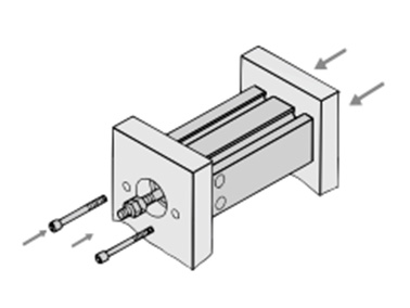
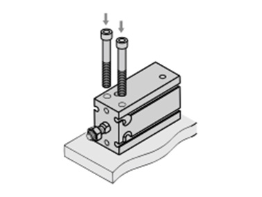
Mounting
Axial mounting (body tapped)
Vertical mounting (body through-holes)
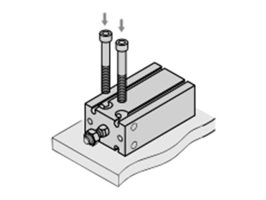
Lateral mounting (body through-holes)
Precautions
Installation and Removal of Retaining Rings
- *Use an appropriate pair of pliers (tool for installing a type C retaining ring) for installation and removal of retaining rings.
- *Even when using an appropriate pair of pliers (tool for installing a type C retaining ring), proceed with caution as there is a danger of the retaining ring flying off the end of the pliers (tool) and causing bodily injury or damage to nearby equipment. After installation, make sure that the retaining ring is securely seated into the retaining ring groove before supplying air.
Selection
- *Operate the cylinder to the stroke end. When the stroke is restricted by an external stopper or a clamped workpiece, sufficient cushioning and noise reduction may not be achieved.
- *Strictly observe the limiting ranges for load weight and maximum speed (Graph 1). Also, the limiting ranges provided here are based on the condition that the cylinder is operated to the stroke end with proper cushion needle adjustment. If operated beyond the limiting ranges, excessive impact will occur and this may cause damage to equipment.
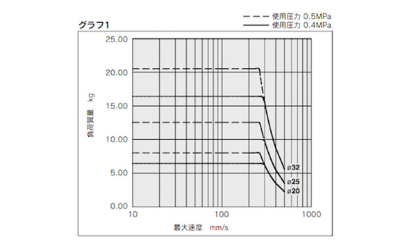
Limiting ranges for load weight and maximum speed (Graph 1)
*See the manufacturer's catalog for product information other than that detailed above.
Codice componente
|
|---|
| CDU20-50A-M9N |
| Codice componente |
Prezzo unitario standard
| Quantità minima d'ordine | Sconto volumi elevati | D.I. cilindro: D (Ø) | Corsa: L (mm) | Temperatura di esercizio (℃) | Pressione di esercizio (MPa) | Port thread type | Auto Switch | Lead Wire Length (m) | Number of Switches | |
|---|---|---|---|---|---|---|---|---|---|---|---|---|
179.74 € | 1 | 26 giorni | 20 | - | - | 0.08~ 0.7 | M5 × 0.8 | M9N | 0.5 | 2 pz. |
Loading...
Informazioni di base
| Metodo di funzionamento cilindro | A doppia azione | Metodo di funzionamento asta | Aste singole | Profilo corpo principale | Cilindro piatto |
|---|---|---|---|---|---|
| Funzione aggiuntiva | Standard | Ambiente, applicazioni | Standard | Bloccaggio estremità | NA |
| Valvole | NA | Tipo di connettore | Assente |
Configura
Proprietà di base
-
Corsa: L(mm)
-
Tipo
- CDU20□
- CDU25□
- CDU32□
- CU20□
- CU25□
- CU32□
-
D.I. cilindro: D(Ø)
-
Port thread type
- G 1/8
- Rc 1/8
- M5 × 0.8
- M5 × 0.8
-
Auto Switch
-
Lead Wire Length(m)
- 0.5
- 3
- Assente
-
Number of Switches
-
Filtrare per tipo dati CAD
- 2D
- 3D
Filtrare per giorni di spedizione standard
-
- Tutti gli articoli
- 4 giorni o meno
- 26 giorni o meno
Attributi opzionali
- Specifiche e dimensioni di alcuni componenti potrebbero non essere illustrate in modo esauriente. Per i dettagli esatti, consultare i cataloghi dei produttori .
Supporto tecnico
Metodo di pagamento


Produzione on demand
Certificati


Copyright © MISUMI Corporation All Rights Reserved.