Dedicated Cutters Recommended Cutting Conditions
Cutting with an O-Ring Groove Cutter
● Use a machine and chuck that have rigidity and high accuracy.
● Select cutting oil suitable for the work material.
● Use F-RGC at feed rates of 50% of the criteria listed below.
Model Number
H-RGC / F-RGC

● Select cutting oil suitable for the work material.
● Use F-RGC at feed rates of 50% of the criteria listed below.
Model Number
H-RGC / F-RGC

Machining by Pinpoint Gate Cutter

Model Number
PGSRC / PM-PGSRC

Model Number
PGC / PM-PGC

Model Number
PGTC / PM-PGTC

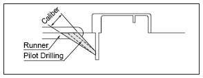
Gate Machining by Submarine Gate Drill
Model Number
SMGC / PM-SMGC / SMBGC / PM-SMBGC / SMEGC / PM-SMEGC

Inverse Taper Machining by Sprue Runner Lock Cutter
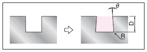
● The following table shows machining conditions when applying gradient to side surfaces.
● With the C-BTEMH, halve the feed rates in the table below when machining.
Model Number
BTEMH / C-BTEMH

Groove Cutting with a Carbide Biting Cutter

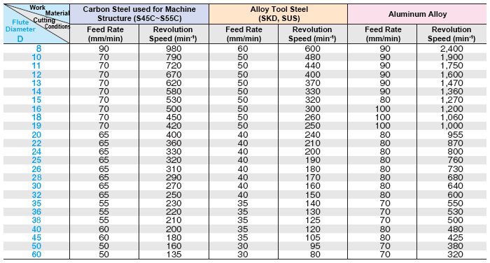
● This table was made based on an Ad (cut depth) of 0.5 to 1.0 D.
● Use a machine and chuck that have rigidity and high accuracy.
● Select cutting oil suitable for the work material.
● If the rotational speed does not increase with your machine, lower the feed rate and rotational speed at the same ratio.
● For fraction sizes of flute diameter D, refer to the larger of the number values.
Model Number
SVKEM / SVKWC

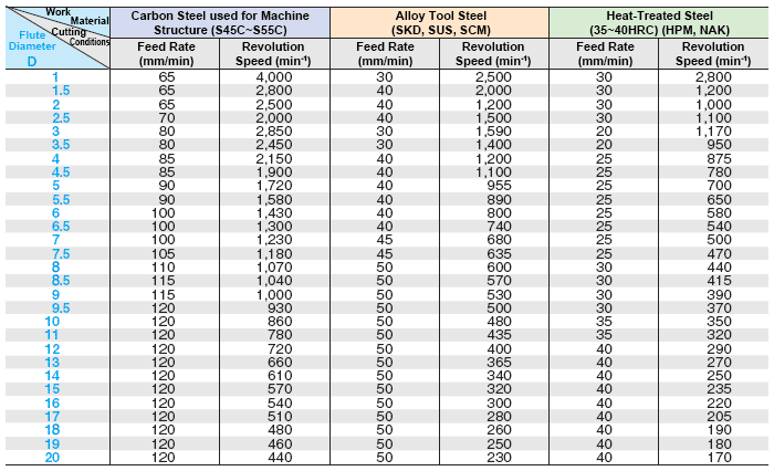
Groove Cutting with a High-Speed Steel End Mill Straight Blade
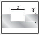
● This table was made based on an Ad (cut depth) of 0.5 D.
● Use a machine and chuck that have rigidity and high accuracy.
● Select cutting oil suitable for the work material.
● Cutting conditions also change when the blade portion is shape-processed. So adjust the optimum cutting conditions by referring to the following.
Model Number
SEMH
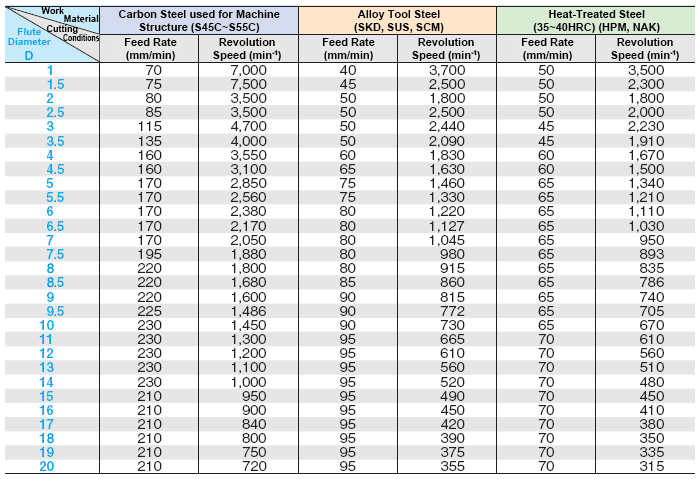
Side-Cutting with a High-Speed Steel End Mill Straight Blade
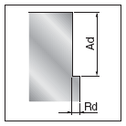
● This table was made based on an Rd (cut width) of 0.1 D and an Ad (cut depth) of 1.5 D.
● Use a machine and chuck that have rigidity and high accuracy.
● Select cutting oil suitable for the work material.
● Cutting conditions also change when the blade portion is shape-processed. So adjust the optimum cutting conditions by referring to the table below.
Model Number
SEMH
Cutting with a Trapezoid Runner Grooving End Mill

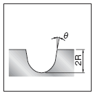
● This table was made based on the machining conditions in the figure above.
● Use a machine and chuck that have rigidity and high accuracy.
● Select cutting oil suitable for the work material.
● If the rotational speed does not increase with your machine, lower the table feed rate and rotational speed at the same ratio.
● TS and XAL coating allows both the feed speed and rotational speed to be increased up to x 150 % in the following conditions.
Model Number
F-RTREM / RTREM

Cutting with a Tapered Bore Runner Grooving End Mill
● Use a machine and chuck that have rigidity and high accuracy.
● Select cutting oil suitable for the work material.
● If the rotational speed does not increase with your machine, lower the table feed rate and rotational speed at the same ratio.
Model Number
RTBEM


