RS2H, cilindro stopper impieghi gravosi (RS2H50-30DM-DS)
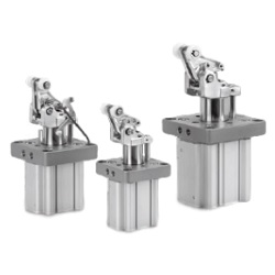
Dettagli del prodotto:
Codice articolo del costruttore: RS2H50-30DM-DS
Marca: SMC
Prezzo: 593.18 €
Tempi di consegna: 26 giorni
Dati Tecnici:
Metodo di funzionamento cilindro: [A doppia azione] A doppia azione
D.I. cilindro: D: 50 Ø
Corsa: L: - mm
Operating Pressure: 1.0 MPa
Port thread type: Rc
(i)Nota
- See catalog for specification details.
- CAD data is not supported for some model numbers
- Product pictures are representations.
Codice componente
Qui sono indicati i codici componente
correlati al prodotto ricercato
RS2H50-30DM-DS
Heavy Duty Stopper Cylinder RS2H Series Specifications
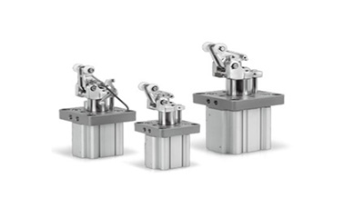
Heavy Duty Stopper Cylinder RS2H Series external appearance
| Tube Internal Diameter (mm) | 50 | 63 | 80 |
|---|---|---|---|
| Operating method | Double acting, double acting spring type, single acting / spring extend | ||
| Rod-end configuration | Lever with built-in shock absorber | ||
| Applicable fluids | Air | ||
| Proof pressure | 1.5 MPa | ||
| Maximum operating pressure | 1.0 MPa | ||
| Ambient temperature and working fluid temperature | -10°C to 60°C (no freezing) | ||
| Lubrication | Not required (non-lube) | ||
| Cushioning | Rubber cushion | ||
| Stroke length tolerance | +1.4 0 | ||
| Mounting | Flange | ||
| Port size (Rc, NPT, G) | 1/8 | 1/4 | 1/4 |
Standard Strokes
(Unit: mm)
| Tube Internal Diameter (mm) | Standard stroke |
|---|---|
| 50 | 30 |
| 63 | 30 |
| 80 | 40 |
Weight list
(Increment: kg)
| Operating method | Rod-end configuration | Tube Internal Diameter (mm) | Weight |
|---|---|---|---|
| Double acting type | Lever with built-in shock absorber | 50 | 1.70 |
| 63 | 2.78 | ||
| 80 | 4.96 |
Structural drawing
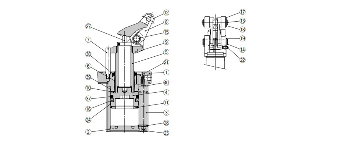
Double acting type (DL, DM) structural drawing
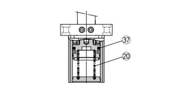
Double acting spring type (BL, BM) structural drawing
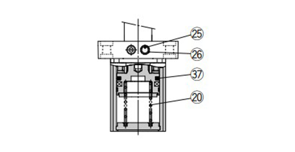
Single acting type (TL, TM)
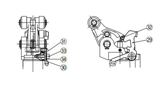
With lock mechanism (-D) structural drawing (option)
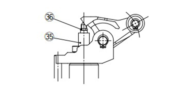
When using cancel cap (-C) structural drawing (option)
Component Parts
| Number | Description | Material | Note |
|---|---|---|---|
| 1 | Rod Cover | Aluminum Alloy | Metallic painted |
| 2 | Bottom plate | Aluminum Alloy | Hard Anodize |
| 3 | Cylinder tube | Aluminum Alloy | Hard Anodize |
| 4 | Piston | Aluminum Alloy | Chromate |
| 5 | Piston rod | Carbon Steel | Hard chrome plated |
| 6 | Bushing | Resin/Copper alloy (Multiple layers) | - |
| 7 | Guide rod | Carbon Steel | Hard chrome plated |
| 8 | Lever | Cast iron | Zinc chromate |
| 9 | Lever holder | Cast iron | Zinc chromate |
| 10 | Bumper A | Urethane | - |
| 11 | Damper B | Urethane | - |
| 12 | Roller | Resin | -□□L |
| Carbon Steel | -□□M | ||
| 13 | Roller pin | Carbon Steel | - |
| 14 | Lever pin | Carbon Steel | - |
| 15 | Lever spring | Steel wire | - |
| 16 | Magnet | - | - |
| 17 | Flat washer | Steel wire | Zinc chromate |
| 18 | C-shaped retaining ring for Shaft | Carbon tool steel | - |
| 19 | C-shaped retaining ring for Shaft | Carbon tool steel | - |
| 20 | Return spring | Steel wire | -T□/-B□ |
| 21 | Hexagon socket head bolt | Chrome Molybdenum Steel | Zinc chromate |
| 22 | Hex Socket Set Screw | Chrome Molybdenum Steel | Zinc chromate |
| 23 | Hexagon socket head plug | Carbon Steel | Zinc chromate |
| 24 | Wear ring | Resin | - |
| 25 | Element | Bronze | -□TL/-□TM |
| 26 | Retaining Ring | Carbon tool steel | -□TL/-□TM |
| 27 | Shock absorber | - | - |
| 28 | Steel ball | Carbon Steel | - |
| 29 | Bracket assembly | Carbon Steel | Used for -D (Lock type) |
| 30 | Bracket spring | Steel wire | Used for -D (Lock type) |
| 31 | Bracket spacer | Carbon Steel | Used for -D (Lock type) |
| 32 | Lock pin | Carbon Steel | Used for -D (Lock type) |
| 33 | Hexagon socket head bolt | Chrome Molybdenum Steel | Used for -D (Lock type) |
| 34 | Flat washer | Carbon Steel | Used for -D (Lock type) |
| 35 | Cancel cap | Aluminum Alloy | Used for -C (Cancel cap type) |
| 36 | O-ring | NBR | Used for -C (Cancel cap type) |
| 37 | Piston Gasket | NBR | - |
| 38 | Rod Gasket | NBR | - |
| 39 | Tube gasket | NBR | - |
| 40 | O-ring | NBR | - |
Replacement Parts / Seal Kit
| Tube Internal Diameter (mm) | Kit No. | Content | ||
|---|---|---|---|---|
| Double acting type | Double acting spring type | Single acting | ||
| 50 | RS2H50D-PS | RS2H50T-PS | Set of nos. above (37) to (40) (excluding [38]) | |
| 63 | RS2H63D-PS | RS2H63T-PS | ||
| 80 | RS2H80D-PS | RS2H80T-PS | ||
- *Seal kit includes (37) to (40) (excluding [38]). Order the seal kit based on each bore size.
- *The seal kit does not include a grease pack, so please order a grease pack separately.
Grease pack part number: GR-S-010 (10 g)
Replacement Parts / Shock Absorber
| Tube Internal Diameter (mm) | Kit No. |
|---|---|
| 50 | RS2H-R50 |
| 63 | RS2H-R63 |
| 80 | RS2H-R80 |
Dimensional Outline Drawing / Output Circuit
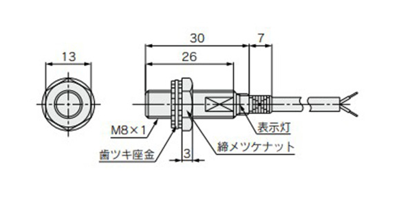
E2E-X2D1-N dimensional outline drawing
(Unit: mm)
*Vinyl insulation round cord
ø3.5 (3.5‑mm diameter) (18/ø0.12 [0.12‑mm diameter]) 2-wire, standard 2 m,
cord extension (individual metal piping) max. 200 m
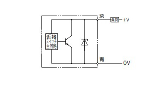
E2E-X2D1-N/2-wire output circuit
Lever Detection Switch (Proximity Switch)
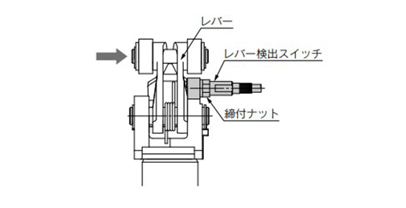
Lever detection switch image 1
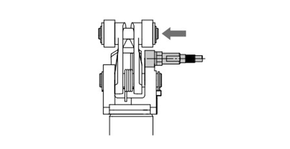
Lever detection switch image 2
| Model | E2E-X2D1-N |
|---|---|
| Output type | Normally open |
| Power supply voltage (Operating voltage range) | 12 to 24 V DC (10 to 30 V DC) Ripple (p-p) 10% max. |
| Current consumption (leakage current) | 0.8 mA or less |
| Response frequency | 1.5 kHz |
| Control output (chest) | 3 to 100 mA |
| Indicator light | Operating indication (red LED), set operation indication (green LED) |
| Ambient operating temperature | -25°C to 70°C (no freezing) |
| Operating ambient humidity | 35 to 95% RH |
| Residual voltageNote 1) | 3 V or less |
| Withstand voltageNote 2) | 1,000 V AC |
| Vibration | Endurance 10 to 55 Hz, double amplitude 1.5 mm, X, Y, Z direction each 2 h |
| Impact | Endurance 500 m/s2(Approx. 50 G) 10 times each in X, Y, Z directions |
| Enclosure | IEC standards IP67 (Immersion proof and oil proof by JEM standards IP67G) |
Note 1) At load current 100 mA and cord length of 2 m
Note 2) Between case and whole live part
Mounting position
Confirm that the proximity switch indicator LED turns to green when the lever is pushed towards the proximity switch side. (Figure 1)
Confirm that the proximity switch indicator LED turns to green when the lever is pushed towards the opposite side from the proximity switch. (Figure 2)
Then, rotate the lever by 90° to confirm that the indicator LED of the proximity switch (red, green) does not turn on.
Fix the cylinder with screws included as accessories after confirming that there is no interference between the lever and the proximity switch.
- *See the manufacturer's catalog for detailed specifications.
- *Product pictures are representations. CAD data is not supported for some model numbers.
- *See the manufacturer's catalog for product information not detailed above.
Codice componente
|
|---|
| RS2H50-30DM-DS |
| Codice componente |
Prezzo unitario standard
| Quantità minima d'ordine | Sconto volumi elevati | Metodo di funzionamento cilindro | D.I. cilindro: D (Ø) | Corsa: L (mm) | Operating Pressure (MPa) | Port thread type | Body Options | Auto Switch | Lead Wire Length (m) | Number of Switches | Head Cover Port Position | Direction of Piping | Materiale rullo | Tipo di connettore | |
|---|---|---|---|---|---|---|---|---|---|---|---|---|---|---|---|---|---|
593.18 € | 1 | 26 giorni | [A doppia azione] A doppia azione | 50 | - | 1.0 | Rc | Con meccanismo di blocco, con interruttore di rilevamento a leva | Senza (magnete incorporato) | - | - | Relazione di posizione di leva e raccordo: standard | Lato flangia | Acciaio al carbonio | - |
Loading...
Informazioni di base
| Metodo di funzionamento asta | Aste singole | Profilo corpo principale | Cilindro piatto | Funzione aggiuntiva | Standard |
|---|---|---|---|---|---|
| Ambiente, applicazioni | Standard | Cushion | Smorzatore in gomma | Rod Tip Shape | Leva con ammortizzatore incorporato |
| Tube Material | Lega di alluminio / Alluminio anodizzato rigido | Specification of cylinder | Cilindro di arresto per impieghi pesanti | Mount Type | Flangia |
Si trova sulla pagina di RS2H, cilindro stopper impieghi gravosi, il codice articolo è il seguente: RS2H50-30DM-DS.
Ulteriori dettagli concernenti specifiche e dimensioni si trovano sotto il codice prodotto RS2H50-30DM-DS.
Configura
Proprietà di base
-
Corsa: L(mm)
-
Lead Wire Length(m)
- 0.5
- 3
- 5
- Connettore a spina M8-3 pin/0,5
- Connettore a spina cavo M12-4 pin A (chiave normale)/0,5
-
Number of Switches
-
Tipo di connettore
- Assente
-
Tipo
- RS2H
- RS2H50
- RS2H63
- RS2H80
-
Metodo di funzionamento cilindro
- A doppia azione
- Ad azione singola (Ritrazione)
- A doppia azione
-
D.I. cilindro: D(Ø)
-
Operating Pressure(MPa)
- 1.0
-
Port thread type
- G
- NPT
- Rc
-
Body Options
- Con cappuccio di annullamento
- Con cappuccio di annullamento, con interruttore di rilevamento a leva
- Con interruttore di rilevamento a leva
- Con meccanismo di blocco
- Con meccanismo di blocco, con cappuccio di annullamento
- Con meccanismo di blocco, con cappuccio di annullamento, con interruttore di rilevamento a leva
- Con meccanismo di blocco, con interruttore di rilevamento a leva
- Senza opzione
-
Auto Switch
-
Head Cover Port Position
- Relazione di posizione di leva e raccordo: 90°
- Relazione di posizione di leva e raccordo: 180°
- Relazione di posizione di leva e raccordo: 270°
- Relazione di posizione di leva e raccordo: Standard
- Relazione di posizione di leva e raccordo: standard
-
Direction of Piping
- Direzione assiale (tubo)
- Lato flangia
-
Materiale rullo
- Acciaio al carbonio
- Resina
-
Filtrare per tipo dati CAD
- 2D
- 3D
Filtrare per giorni di spedizione standard
-
- Tutti gli articoli
- 4 giorni o meno
- 10 giorni o meno
- 12 giorni o meno
- 26 giorni o meno
- 39 giorni o meno
- 68 giorni o meno
Attributi opzionali
- Product pictures are representations.
- Specifiche e dimensioni di alcuni componenti potrebbero non essere illustrate in modo esauriente. Per i dettagli esatti, consultare i cataloghi dei produttori .
Tipologia prodotto
| Codice componente |
|---|
| RS2H50-30BL-DC |
| RS2H50-30BL-DS |
| RS2H50-30BL-DSQ |
| RS2H50-30DM-DS-M9BW |
| RS2H50-30DM-DSP |
| RS2H50-30DM-DSQ |
| Codice componente | Prezzo unitario standard | Quantità minima d'ordine | Sconto volumi elevati | Giorni spedizione standard ? | Metodo di funzionamento cilindro | D.I. cilindro: D (Ø) | Corsa: L (mm) | Operating Pressure (MPa) | Port thread type | Body Options | Auto Switch | Lead Wire Length (m) | Number of Switches | Head Cover Port Position | Direction of Piping | Materiale rullo | Tipo di connettore |
|---|---|---|---|---|---|---|---|---|---|---|---|---|---|---|---|---|---|
467.00 € | 1 | 26 giorni | [A doppia azione] Con molla di richiamo | 50 | - | 1.0 | Rc | Con meccanismo di blocco, con cappuccio di annullamento | Senza (magnete incorporato) | - | - | Relazione di posizione di leva e raccordo: standard | Lato flangia | Resina | - | ||
593.18 € | 1 | 26 giorni | [A doppia azione] Con molla di richiamo | 50 | - | 1.0 | Rc | Con meccanismo di blocco, con interruttore di rilevamento a leva | Senza (magnete incorporato) | - | - | Relazione di posizione di leva e raccordo: standard | Lato flangia | Resina | - | ||
593.18 € | 1 | 26 giorni | [A doppia azione] Con molla di richiamo | 50 | - | 1.0 | Rc | Con meccanismo di blocco, con interruttore di rilevamento a leva | Senza (magnete incorporato) | - | - | Relazione di posizione di leva e raccordo: 180° | Lato flangia | Resina | - | ||
660.81 € | 1 | 26 giorni | [A doppia azione] A doppia azione | 50 | - | 1.0 | Rc | Con meccanismo di blocco, con interruttore di rilevamento a leva | M9BW | 0.5 | 2 pz. | Relazione di posizione di leva e raccordo: standard | Lato flangia | Acciaio al carbonio | - | ||
593.18 € | 1 | 26 giorni | [A doppia azione] A doppia azione | 50 | - | 1.0 | Rc | Con meccanismo di blocco, con interruttore di rilevamento a leva | Senza (magnete incorporato) | - | - | Relazione di posizione di leva e raccordo: 270° | Lato flangia | Acciaio al carbonio | - | ||
593.18 € | 1 | 26 giorni | [A doppia azione] A doppia azione | 50 | - | 1.0 | Rc | Con meccanismo di blocco, con interruttore di rilevamento a leva | Senza (magnete incorporato) | - | - | Relazione di posizione di leva e raccordo: 180° | Lato flangia | Acciaio al carbonio | - |


