M(D)U Cilindro a pistone ovale, Doppio effetto, Stelo semplice con scanalatura di montaggio sensori

- In Offerta
[Features]
· Auto switches can be mounted easily.
· Can be mounted without brackets and in flexible ways.
· Can be mounted with a short pitch.
· Various brackets are available to accommodate a wide range of applications.
(i)Nota
- See catalog for specification details.
- Product pictures are representations. CAD data is not supported for some model numbers.
Codice componente
Qui sono indicati i codici componente
correlati al prodotto ricercato
Plate Cylinder, Double Acting, Single Rod MU Series Specifications
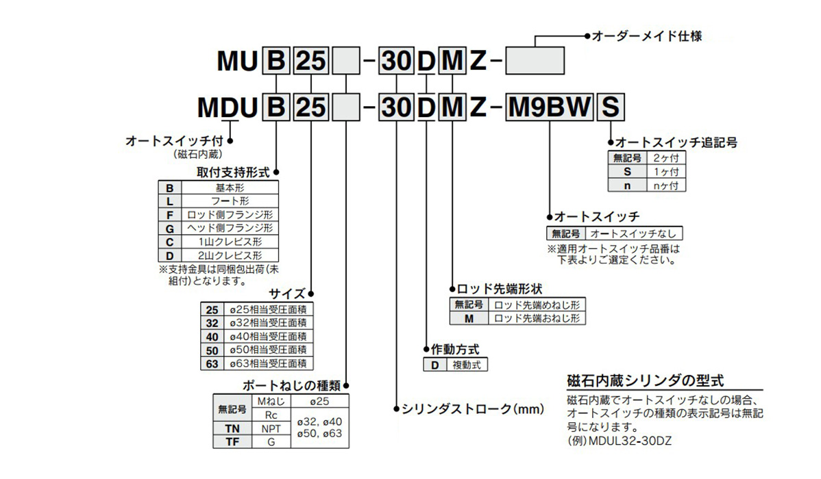
Model Number Notation

Model number notation: images
Applicable Auto Switches
| Type | Special functions | Wire Exit | Indicator light | Wiring (output) | Load Voltage | Auto switch model number | Lead wire length (m) | Pre-Wired Connector | Applicable load | |||||||
|---|---|---|---|---|---|---|---|---|---|---|---|---|---|---|---|---|
| DC | AC | Vertical Outlet | Lateral Outlet | 0.5 (Nil) | 1 (M) | 3 (L) | 5 (Z) | |||||||||
| Solid state auto switch | - | Grommet | Yes | 3-wire (NPN) | 24 V | 5 V, 12 V | - | M9NV | M9N | ● | ● | ● | ○ | ○ | IC circuit | Relay, PLC |
| 3-wire (PNP) | M9PV | M9P | ● | ● | ● | ○ | ○ | |||||||||
| 2-Wire | 12 V | M9BV | M9B | ● | ● | ● | ○ | ○ | - | |||||||
| Diagnostic indication (2-color indicator) | 3-wire (NPN) | 5 V, 12 V | M9NWV | M9NW | ● | ● | ● | ○ | ○ | IC circuit | ||||||
| 3-wire (PNP) | M9PWV | M9PW | ● | ● | ● | ○ | ○ | |||||||||
| 2-Wire | 12 V | M9BWV | M9BW | ● | ● | ● | ○ | ○ | - | |||||||
| Improved water resistance product (2-color indicator) | 3-wire (NPN) | 5 V, 12 V | *1M9NAV | *1M9NA | ○ | ○ | ● | ○ | ○ | IC circuit | ||||||
| 3-wire (PNP) | *1M9PAV | *1M9PA | ○ | ○ | ● | ○ | ○ | |||||||||
| 2-Wire | 12 V | *1M9BAV | *1M9BA | ○ | ○ | ● | ○ | ○ | - | |||||||
| Strong magnetic field resistant (2-color indicator) | 2-wire (non-polar) | - | - | P3DWANote 2) | ● | - | ● | ● | ○ | |||||||
| Reed switch | - | Grommet | Yes | 3-wire (NPN equivalent) | - | 5 V | - | A96V | A96 | ● | - | ● | - | - | IC circuit | - |
| 2-Wire | 24 V | 12 V | 100 V | *2A93V | A93 | ● | ● | ● | ● | - | - | Relay, PLC | ||||
| NA | 100 V or less | A90V | A90 | ● | - | ● | - | - | IC circuit | |||||||
- *1Water resistant type auto switches can be mounted on the above models, but in this case, the water resistance cannot be guaranteed. Check with the manufacturer regarding water-resistant types for the above model numbers.
- *21 m lead wire is only applicable to D-A93.
- *Auto switch is shipped together (not assembled).
- *Note 1) The D-M9□V, M9□WV, M9□AV and A9□V auto switches cannot be mounted on the ported surface with some cylinder strokes and sizes of fittings. This should be checked in advance.
- *Note 2) The strong magnetic field resistant auto switch (D-P3DWA□) is from the previous MU series.
Specifications Table
| Tube Internal Diameter (mm) | 25 | 32 | 40 | 50 | 63 |
|---|---|---|---|---|---|
| Operating method | Double acting, single rod | ||||
| Applicable fluids | Air | ||||
| Proof pressure | 1.05 MPa | ||||
| Maximum operating pressure | 0.7 MPa | ||||
| Minimum operating pressure | 0.05 MPa | ||||
| Ambient temperature and working fluid temperature | -10 to 60°C | ||||
| Lubrication | Not required (non-lube) | ||||
| Operating piston speed | 50 to 500 mm/s | ||||
| Stroke length tolerance | (0 to +1.4) | ||||
| Cushioning | Rubber cushion | ||||
| Mounting style | Foot type, rod-end flange type, head-end flange type single-clevis type, double-clevis type | ||||
| Rod-end configuration | Rod-end male thread, Rod-end female thread | ||||
| Allowable rotational torque | 0.25 N·m | 0.55 N·m | 1.25 N·m | 2.0 N·m | |
| Rod non-rotating accuracy | ±1° | ±0.8° | ±0.5° | ||
Standard Strokes
(Unit: mm)
| Size | Standard stroke | Maximum manufacturable stroke |
|---|---|---|
| 25, 32, 40 50, 63 | 5, 10, 15, 20, 25, 30, 35, 40, 45, 50 75, 100, 125, 150, 175, 200, 250, 300 | 300 |
Made to order specifications
| Indicator symbol | Specifications/contents |
|---|---|
| -XA□ | Change of rod-end shape |
| -XC6 | Stainless steel |
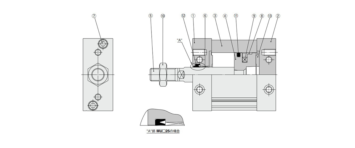
Structural drawing

Plate Cylinder, Double Acting, Single Rod MU Series Structural Drawing
Component Parts
| Number | Description | Material | Note |
|---|---|---|---|
| 1 | Rod Cover | Aluminum Alloy | Anodized |
| 2 | Head cover | Aluminum Alloy | Anodized |
| 3 | Cylinder tube | Aluminum Alloy | Hard Anodize |
| 4 | Piston | Die-cast aluminum | Chromate |
| 5 | Piston rod | Carbon steel | Hard chrome plated |
| 6 | Bushing | Resin/Copper alloy (Multiple layers) | - |
| 7 | Hexagon socket head bolt | Stainless steel | - |
| 8 | Wear ring | Resin | - |
| 9 | Magnet | - | Only built-in magnet type |
| 10 | Rod-end nut | Rolled Steel | Only attached to the rod-end male thread |
| 11 | Piston Gasket | NBR | - |
| 12 | Rod Gasket | NBR | - |
| 13 | Dampers | Urethane | - |
Replacement Parts / Seal Kit
| Tube Internal Diameter (mm) | Order number | Content |
|---|---|---|
| 25 | MUB25-PS | Set of above numbers (11), (12), (13) |
| 32 | MUB32-PS | |
| 40 | MUB40-PS | |
| 50 | MUB50-PS | |
| 63 | MUB63-PS |
- *Seal kit includes (11) to (13). Order the seal kit based on each bore size.
- *Since the seal kit does not include a grease pack, order it separately.
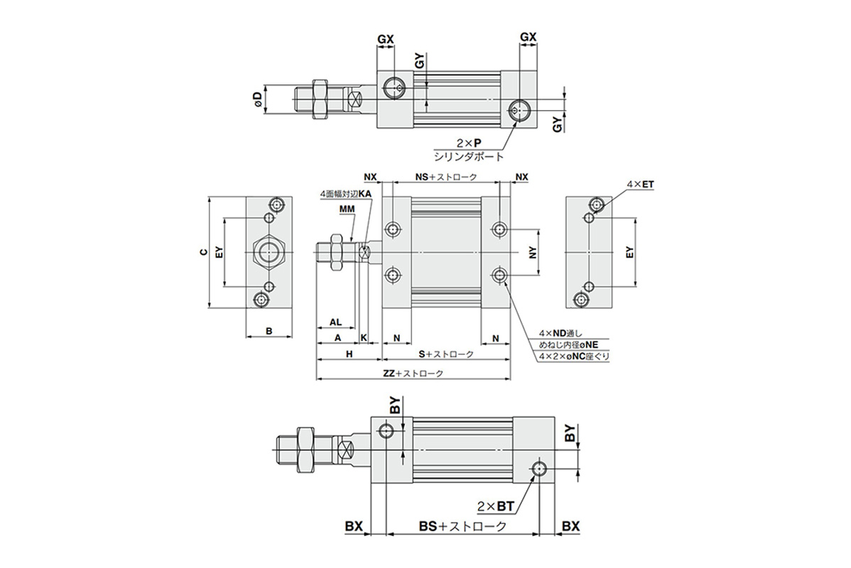
Plate Cylinder, Double Acting, Single Rod MU Series Dimensions
Male rod end

Male rod end dimensional drawing
(Unit: mm)
| Model | Stroke range (mm) | A | AL | B | BS | BT | BX | BY | C | D | ET | EY | GX | GY | H | K | KA |
|---|---|---|---|---|---|---|---|---|---|---|---|---|---|---|---|---|---|
| MUB25 | 5 to 300 | 22 | 19.5 | 24 | 37 | M5 ×; 0.8 depth 7.5 | 9 | 7 | 54 | 12 | M5 ×; 0.8 depth 11 | 26 | 10 | 5 | 36 | 5.5 | 10 |
| MUB32 | 5 to 300 | 26 | 23.5 | 28 | 45 | M6 ×; 1 depth 12 | 6.5 | 8 | 68 | 14 | M6 ×; 1 depth 11 | 42 | 8.5 | 5.5 | 40 | 5.5 | 12 |
| MUB40 | 5 to 300 | 30 | 27 | 32 | 44 | M8 ×; 1.25 depth 13 | 8 | 9 | 86 | 16 | M8 ×; 1.25 depth 11 | 54 | 9 | 7 | 45 | 6 | 14 |
| MUB50 | 5 to 300 | 35 | 32 | 39 | 54 | M10 ×; 1.5 depth 14.5 | 10 | 9 | 104 | 20 | M10 ×; 1.5 depth 15 | 64 | 11.5 | 8 | 53 | 7 | 18 |
| MUB63 | 5 to 300 | 35 | 32 | 50 | 53 | M12 ×; 1.75 depth 18 | 11 | 12 | 124 | 20 | M12 ×; 1.75 depth 15 | 72 | 11.5 | 10 | 56 | 7 | 18 |
| Model | MM | N | NC | ND | NE | NS | NX | NY | P | S | ZZ | ||
|---|---|---|---|---|---|---|---|---|---|---|---|---|---|
| - | TN | TF | |||||||||||
| MUB25 | M10 ×; 1.25 | 16.5 | 7.5 depth 4.5 | M5 ×; 0.8 | 4.3 | 43 | 6 | 26 | M5 ×; 0.8 | - | - | 55 | 91 |
| MUB32 | M12 ×; 1.25 | 18 | 9 depth 5.5 | M6 ×; 1 | 5.1 | 45 | 6.5 | 28 | Rc 1/8 | NPT 1/8 | G 1/8 | 58 | 98 |
| MUB40 | M14 ×; 1.5 | 18.5 | 10.5 depth 6.5 | M8 ×; 1.25 | 6.9 | 44 | 8 | 36 | Rc 1/8 | NPT 1/8 | G 1/8 | 60 | 105 |
| MUB50 | M18 ×; 1.5 | 24 | 13.5 depth 8.5 | M10 ×; 1.5 | 8.7 | 54 | 10 | 42 | Rc 1/4 | NPT 1/4 | G 1/4 | 74 | 127 |
| MUB63 | M18 ×; 1.5 | 24 | 17 depth 10.5 | M12 ×; 1.75 | 10.5 | 53 | 11 | 46 | Rc 1/4 | NPT 1/4 | G 1/4 | 75 | 131 |
Female rod end

Female rod end dimensional drawing
- *Dimensions other than the above are the same as the male thread type. However, K/KA dimensions are the same as the male thread type.
(Unit: mm)
| Model | H | MM | ZZ |
|---|---|---|---|
| MUB25 | 14 | M6 ×; 1 depth 12 | 69 |
| MUB32 | 14 | M8 ×; 1.25 depth 13 | 72 |
| MUB40 | 15 | M8 ×; 1.25 depth 13 | 75 |
| MUB50 | 18 | M10 ×; 1.5 depth 15 | 92 |
| MUB63 | 21 | M10 ×; 1.5 depth 15 | 96 |
- **The position of the 4 flats of the piston rod is ±3° in relation to the cylinder side surface.
Rod-end nut

Rod-end nut dimensional drawing
| Model Number | Size | d | H1 | B1 | C1 | D1 |
|---|---|---|---|---|---|---|
| NT-03 | 25 | M10 ×; 1.25 | 6 | 17 | 19.6 | 16.5 |
| NT-MU03 | 32 | M12 ×; 1.25 | 7 | 19 | 21.9 | 18 |
| NT-04 | 40 | M14 ×; 1.5 | 8 | 22 | 25.4 | 21 |
| NT-05 | 50, 63 | M18 ×; 1.5 | 11 | 27 | 31.2 | 26 |
Codice componente
|
|---|
| 20-MDUB40TF-40DZ |
| 20-MDUB63TF-25DZ |
| Codice componente |
Prezzo unitario standard
| Quantità minima d'ordine | Sconto volumi elevati | Profilo corpo principale | D.I. cilindro: D (Ø) | Corsa: L (mm) | Ambiente, applicazioni | Bloccaggio estremità | Valvole | Pressione di esercizio (MPa) | Operating Pressure (MPa) | Specifications | Port thread type | Auto Switch | Lead Wire Length (m) | Number of Switches | Type of Mount Support | Rod Tip Shape | Tipo di connettore | |
|---|---|---|---|---|---|---|---|---|---|---|---|---|---|---|---|---|---|---|---|---|
103.71 € | 1 | 26 giorni | [Profilo blocco] Cilindro a piastre | 40 | - | Nessun uso con materiali diversi da quelli a base di rame, teflon (Placcatura parziale) | NA | NA | 0.05~ 0.7 | - | Magnete incorporato | G | Senza interruttore | - | - | Tipo base | Estremità asta femmina | Assente | ||
146.31 € | 1 | 26 giorni | [Profilo blocco] Cilindro a piastre | 63 | - | Nessun uso con materiali diversi da quelli a base di rame, teflon (Placcatura parziale) | NA | NA | 0.05~ 0.7 | - | Magnete incorporato | G | Senza interruttore | - | - | Tipo base | Estremità asta femmina | Assente |
Loading...
Informazioni di base
| Metodo di funzionamento cilindro | A doppia azione | Metodo di funzionamento asta | Aste singole | Funzione aggiuntiva | Standard |
|---|---|---|---|---|---|
| Cushion | Smorzatore in gomma | Custom-made Specifications | Assente |
Configura
Proprietà di base
-
Profilo corpo principale
- Profilo blocco
- Profilo blocco
-
D.I. cilindro: D(Ø)
-
Corsa: L(mm)
-
Bloccaggio estremità
- NA
-
Valvole
- NA
-
Operating Pressure(MPa)
- 0.05–0.7
-
Specifications
- Magnete incorporato
- Senza magnete
-
Port thread type
- G
- NPT
- Rc
- Vite M
-
Auto Switch
-
Lead Wire Length(m)
- 0,5 (connettore a spina M8 a 3 pin)
- 0,5 [connettore a spina cavo A M12 a 4 pin (chiave normale)]
- 0.5
- 3
- 5
-
Number of Switches
-
Type of Mount Support
- Cavallotto singolo
- Con piede
- Flangia lato testa
- Perno a U
- Piede
- Tipo a doppia cerniera
- Tipo base
- Tipo flangia estremità asta
-
Rod Tip Shape
- Estremità asta femmina
- Estremità asta maschio
-
Tipo di connettore
- M12 4 pin
- Assente
-
Tipo
- 20-MDU
- MDU
- MU
-
Ambiente, applicazioni
- Standard
- Nessun uso con materiali diversi da quelli a base di rame, teflon (Placcatura parziale)
-
Filtrare per tipo dati CAD
- 2D
- 3D
Filtrare per giorni di spedizione standard
-
- Tutti gli articoli
- Stesso giorno
- 4 giorni o meno
- 15 giorni o meno
- 22 giorni o meno
- 26 giorni o meno
- 39 giorni o meno
Attributi opzionali
- Specifiche e dimensioni di alcuni componenti potrebbero non essere illustrate in modo esauriente. Per i dettagli esatti, consultare i cataloghi dei produttori .


