Benvenuti nel nuovo catalogo elettronico MISUMI!
Abbiamo aggiornato i nostri sistemi online! Scoprite di più qui.
- Tipo
- Applicazione
- Numero di attacchi
- Metodo di installazione
- Caratteristiche
- Numero di solenoidi
- Tipo singolo
- Tipo singolo
- A commutazione
- Tensione
- Tipo di azionamento
- Con tenuta
- Pressione nominale(MPa)
- Mandata aria pilota
- Interruttore manuale
- Specifiche bobina
- Ingresso elettrico conduttore
- Spia / circuito di protezione
- Opzioni corpo
- Tipo
- CAD
- 2D
- 3D
- Giorni di spedizione est.
- Tutti
- Entro 26 giorni lavorativi
VF3000, Elettrovalvola a 5 vie con Raddrizzatore (VF5144-5DE1)

Attenzione
- Le immagini dei prodotti possono essere rappresentative. Fare riferimento al catalogo del produttore per i dettagli.
Informazioni sul prodotto
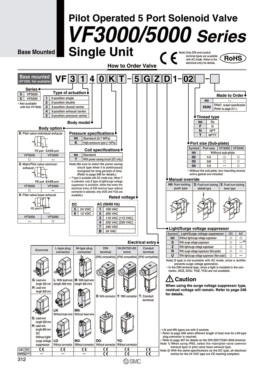
5-Port Pilot Type Solenoid Valve VF3000/VF5000 Series, Base Mounted Type, Single Unit Specifications
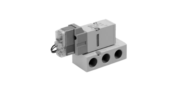
VF3000 Series external appearance
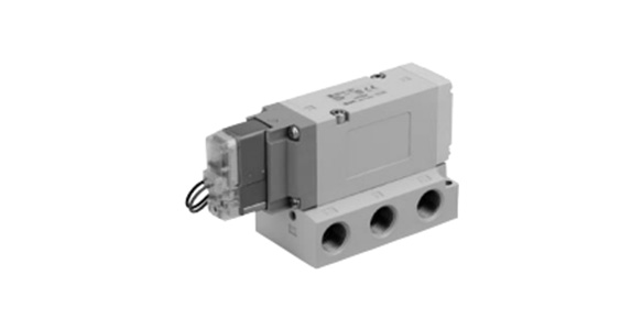
VF5000 Series external appearance
| Model | VF3000 | VF5000 | ||
|---|---|---|---|---|
| Usable Fluids | Air | |||
| Operating Pressure Range MPa | Standard | 2 position single, 3 position | 0.15 to 0.7 | |
| 2-position double | 0.1 to 0.7 | |||
| High-pressure | 2 position single, 3 position | 0.15 to 1.0 | ||
| 2-position double | 0.1 to 1.0 | |||
| Ambient Temperature and Operating Fluid Temperature °C | -10 to 50 (no freezing) | |||
| Maximum Operating Frequency Hz | 2-position single/double | 10 | 5 | |
| 3 Position | 3 | 3 | ||
| Manual Operation | Non-locking, push type Push-turn locking slotted type Push-turn locking hand-operated type | |||
| Pilot Exhaust Method | Individual exhaust main valve / pilot valve common exhaust | Pilot valve: base exhaust type | ||
| Lubrication | Not required | |||
| Mounting Orientation | Free | |||
| Impact Resistance / Vibration Resistance: m/s2 *1: | 300/50 | |||
| Enclosure | Dust-proof (D, Y, T are IP65*2) | |||
*1: Impact resistance: No malfunctions after testing under the following conditions: in the axial direction and at a right angle to the main valve and armature in both energized and non-energized states (once for each condition state). (Initial value)
Vibration resistance: No malfunctions occurred in a 1-sweep test between 45 and 2,000 Hz. The test was performed in both energized and non-energized states and in the axial direction and at right angles to the main valve and armature. (Initial value)
*2: Based on IEC60529. When using with IP65, select the main/pilot valve common exhaust type or pilot valve base exhaust type.
Solenoid Specifications
| Electrical Entry | Grommet (G), (H) L-type plug connector (L) M-type plug connector (M) | DIN terminal (D) DIN (EN175301-803) terminal (Y) Conduit terminal (T) | ||
|---|---|---|---|---|
| G, H, L, M | D, Y, T | |||
| Coil rated voltage (V) | DC | 24, 12 | ||
| AC (50/60 Hz) | 24, 100, 110, 200, 220, 240 | |||
| Allowable Voltage Fluctuation | ±10% of rated voltage * | |||
| Power Consumption W | DC | Standard | 1.5 (with indicator light: 1.55) | 1.5 (with light 1.75) |
| With power saving circuit | 0.55* (only with light) [Inrush 1.55, Holding 0.55] | 0.75* (only with light) [Inrush 1.75, Holding 0.75] | ||
| Apparent power VA * | AC | 24 V | 1.5 (with indicator light: 1.55) | 1.5 (with light 1.75) |
| 100 V | 1.55 (with light 1.65) | 1.55 (with light 1.7) | ||
| 110 V [115 V] | ||||
| 200 V | ||||
| 220 V [230 V] | ||||
| 240 V | ||||
| Surge Voltage Suppressor | Diode (varistor for non-polar type) | |||
| Indicator Light | LED (neon bulb for AC mode of D, Y, T) | |||
- *The 110 V AC and 115 V AC types are interchangeable. The 220 V AC and 230 V AC types are also interchangeable.
- For 115 V AC and 230 V AC, the allowable voltage fluctuation is -15 to +5% of the rated voltage.
- As the S, Z, and T types (with power saving circuit) have voltage drop due to the internal circuits, the allowable voltage fluctuation should be within the range given below.
24 V DC: -7 to +10%
12 V DC: -4% to +10%
Response Time
| Series | Switching Method | Pressure Specification | Operating Pressure Range MPa | Response Time ms (at 0.5 MPa) | ||||
|---|---|---|---|---|---|---|---|---|
| Without indicator light / surge voltage protection circuit | With light and surge voltage suppressor | AC | ||||||
| S, Z Type | R, U Type | |||||||
| VF3000 | 2 Position | Single | Standard Type | 0.15 to 0.7 | 20 | 45 | 23 | 45 |
| Double | 0.1 to 0.7 | 12 | 12 | 12 | 12 | |||
| 3 Position | 0.15 to 0.7 | 30 | 55 | 33 | 55 | |||
| 2 Position | Single | High-pressure type | 0.15 to 1.0 | 23 | 48 | 26 | 48 | |
| Double | 0.1 to 1.0 | 15 | 15 | 15 | 15 | |||
| 3 Position | 0.15 to 1.0 | 33 | 58 | 36 | 58 | |||
| VF5000 | 2 Position | Single | Standard Type | 0.15 to 0.7 | 30 | 55 | 33 | 55 |
| Double | 0.1 to 0.7 | 15 | 15 | 15 | 15 | |||
| 3 Position | 0.15 to 0.7 | 50 | 75 | 53 | 75 | |||
| 2 Position | Single | High-pressure type | 0.15 to 1.0 | 33 | 58 | 36 | 58 | |
| Double | 0.1 to 1.0 | 18 | 18 | 18 | 18 | |||
| 3 Position | 0.15 to 1.0 | 53 | 78 | 56 | 78 | |||
*Based on JIS B8375:1981 dynamic performance testing. (Coil temperature 20°C, at rated voltage)
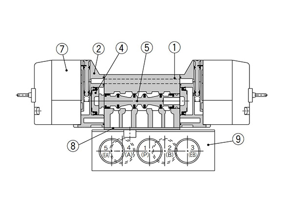
Structure Drawings / Base Mounted Type
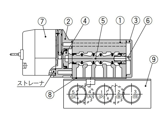
2 position single structure drawing
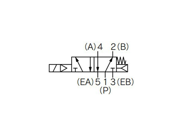
2-position single indicator symbol
2-position double structure drawing
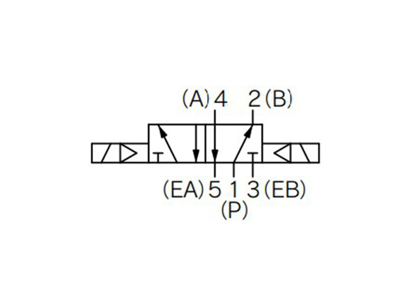
2-position double display symbol
Component Parts
| Number | Part name | Material | Note |
|---|---|---|---|
| 1 | Body | Die-cast aluminum | Urban white |
| 2 | Adapter Plate | Resin | Urban gray |
| 3 | End Plate | Resin | Urban white |
| 4 | Piston | Resin | - |
| 5 | Spool Valve | Aluminum, HNBR | - |
| 6 | Spring | SUS | - |
| Number | Part name | Note |
|---|---|---|
| 7 | Pilot Valve Assembly | Built-in strainer |
| 8 | Gasket | HNBR |
| 9 | Sub-plate | Die-cast aluminum |
| - | Small cross-head/straight-slot combination pan head screw (1 pc.) | For valve mounting |
| - | Hexagon Socket Head Screw (×1) | For valve mounting |
*Valve mount tightening torque M4: 1.4 N⋅m
Drawings / VF3000 Series Base Mounted Type
2-position single
(Unit: mm)
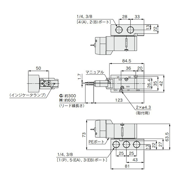
Grommet (G) (H): VF3140-□G/H□□1-02/03□ dimensional drawings
(Unit: mm)
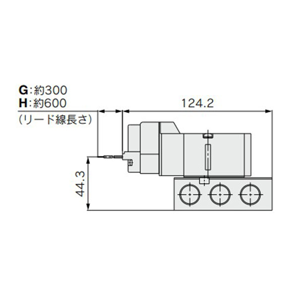
Grommet (G) (H) DC specification without indicator light / surge voltage suppressor dimensional drawing
(Unit: mm)
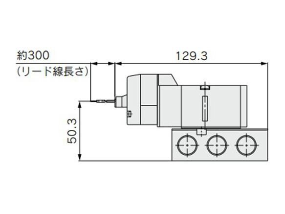
L plug connector (L): VF3140-□L□□1-02/03□ dimensional drawing
*Dimensions same as grommet (G) when not specified.
(Unit: mm)
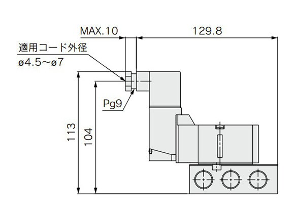
DIN terminal (D) (Y): VF3140-□D/Y□□1-02/03□ dimensional drawing
*Dimensions same as grommet (G) when not specified.
Precautions
- *When using the surge voltage suppressor type, residual voltage will remain. See the manufacturer's catalog for details.
- *See the manufacturer's catalog for information other than the above.
Ulteriori informazioni
Informazioni di base
SMC Solenoid Valve.
[Features]
· Built-in full-wave rectifier
· The pilot valve features a built-in strainer
Attenzione
- Le immagini dei prodotti possono essere rappresentative. Fare riferimento al catalogo del produttore per i dettagli.