JC, Giunto snodato, Tipo standard, leggero (JC40-14-150)

Dettagli del prodotto:
Codice articolo del costruttore: JC40-14-150
Marca: SMC
Prezzo: 36.81 €
Tempi di consegna: 4 giorni
Dati Tecnici:
Filettatura di collegamento nominale M: M10–M18 mm
Filettatura di collegamento nominale p: 1–1.75 mm
Max. Forza di trazione di esercizio: 1.25 kN
Disallineamento U ammesso: 0.75 mm
Dimensione foro applicabile: 40 ø
(i)Nota
- Le immagini dei prodotti possono essere immagini rappresentative. Fare riferimento al catalogo per i dettagli.
Codice componente
Qui sono indicati i codici componente
correlati al prodotto ricercato
JC40-14-150
JC Series Floating Joint, Light Weight Type For Light Load Specifications
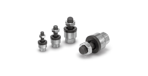
JC Series Floating Joint external appearance
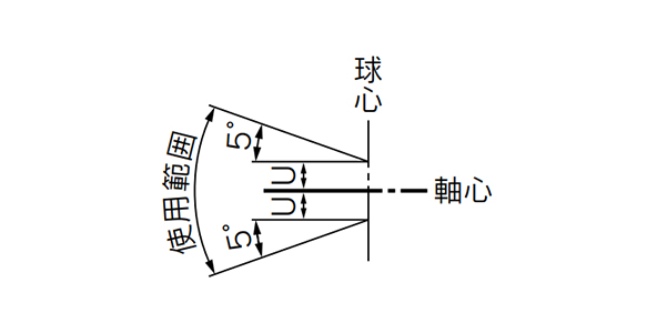
JC Series Floating Joint operating range
| Model | Application Cylinder tube bore size (mm) | Compatible cylinder nominal thread size | Maximum operating tension and compression force (N) | Allowable eccentricity U (mm) | Rotating angle |
|---|---|---|---|---|---|
| Basic type | |||||
| Standard / Thread nominal size | |||||
| JC20-8-125 | 20 | M8 ×; 1.25 | 300 | 0.5 | ±5 ° |
| JC30-10-125 | 25, 32 | M10 ×; 1.25 | 800 | 0.5 | |
| JC40-14-150 | 40 | M14 ×; 1.5 | 1,250 | 0.75 | |
| JC63-18-150 | 50/63 | M18 ×; 1.5 | 3,100 | 1 | |
| Semi-standard / Thread nominal size | |||||
| JC20-8-100 | 20 | M8 ×; 1 | 300 | 0.5 | ±5 ° |
| JC25-10-150 | 25 | M10 ×; 1.5 | 800 | 0.5 | |
| JC32-10-100 | 32 | M10 ×; 1 | 800 | 0.5 | |
| JC40-12-125 | 32/40 | M12 ×; 1.25 | 1,250 | 0.75 | |
| JC40-12-150 | 40 | M12 ×; 1.5 | 1,250 | 0.75 | |
| JC40-12-175 | 32/40 | M12 ×; 1.75 | 1,250 | 0.75 | |
| JC50-16-150 | 50 | M16 ×; 1.5 | 3,100 | 1 | |
| JC63-16-200 | 50/63 | M16 ×; 2 | 3,100 | 1 | |
(Standard Type / Pneumatic: Up to 1 MPa) Dimensions
(Unit: mm)

JC Series Floating Joint dimensional drawing
| Model | Application cylinder bore size | M | A | B | D | E | F | G | H | Center of sphere R | Maximum thread depth P | Allowable eccentricity U | Maximum operating tensile and compressive force N | Weight kg | |
|---|---|---|---|---|---|---|---|---|---|---|---|---|---|---|---|
| Nominal diameter | Pitch | ||||||||||||||
| JC20-8-125 | 20 | 8 | 1.25 | 44 | 17.5 | 21 | 4.5 | 7 | 7 | 13 | 30.5 | 8 | 0.5 | 300 | 0.03 |
| JC30-10-125 | 25/32 | 10 | 1.25 | 49.5 | 19.5 | 24 | 5 | 8 | 8 | 17 | 34 | 9 | 0.5 | 800 | 0.05 |
| JC40-14-150 | 40 | 14 | 1.5 | 60 | 20 | 31 | 6 | 11 | 11 | 22 | 38 | 13 | 0.75 | 1,250 | 0.12 |
| JC63-18-150 | 50/63 | 18 | 1.5 | 74.5 | 25 | 41 | 7.5 | 14 | 13.5 | 27 | 47.5 | 15 | 1 | 3,100 | 0.23 |
Diagram
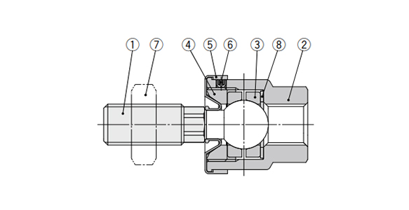
JC Series Floating Joint Diagram
| Number | Description | Material | Note |
|---|---|---|---|
| 1 | Stud | Steel | Manganese phosphate |
| 2 | Case | Aluminum | Chromate |
| 3 | Ring | Steel | - |
| 4 | Cap | Steel | Black zinc chromated |
| 5 | Dust cover | Synthetic rubber | - |
| 6 | Set screw | Steel | Zinc chromate |
| 7 | Rod end nut | Steel | Zinc chromate |
| 8 | Washer | Steel | - |
Rod-end Nut (Accessory) dimensional drawing
(Unit: mm)
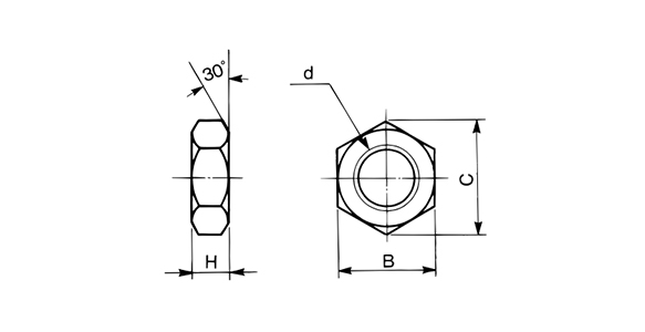
Rod-end nut dimensional drawing
| Model | d: thread nominal size | H | B | C |
|---|---|---|---|---|
| JC20-8-100 | M8 ×; 1 | 5 | 13 | 15 |
| JC20-8-125 | M8 ×; 1.25 | 5 | 13 | 15 |
| JC32-10-100 | M10 ×; 1 | 6 | 17 | 19.6 |
| JC30-10-125 | M10 ×; 1.25 | 6 | 17 | 19.6 |
| JC25-10-150 | M10 ×; 1.5 | 6 | 17 | 19.6 |
| JC40-12-125 | M12 ×; 1.25 | 7 | 19 | 21.9 |
| JC40-12-150 | M12 ×; 1.5 | 7 | 19 | 21.9 |
| JC40-12-175 | M12 ×; 1.75 | 7 | 19 | 21.9 |
| JC40-14-150 | M14 ×; 1.5 | 8 | 22 | 25.4 |
| JC50-16-150 | M16 ×; 1.5 | 10 | 24 | 27.7 |
| JC63-16-200 | M16 ×; 2 | 10 | 24 | 27.7 |
| JC63-18-150 | M18 ×; 1.5 | 11 | 27 | 31.2 |
Precautions
- *When screwing the male threads of the rod into the female threads of the socket or the case, make sure that the rod does not bottom out.
- *The dust cover may stick to the stud. Move the dust cover at the base of the stud with your fingers, or twist the stud right and left gently to free it.
- *When using a floating joint to connect the cylinder rod to a driven body, secure it in place by applying a torque that is appropriate for the thread size. Also, if there is a risk of loosening during operation, take measures to prevent loosening, such as using a locking pin or thread adhesive.
- *This product is dedicated to linear motion. The threaded portion can be rotated, but this product is not a rotary joint. It cannot be used for rotational applications.
- *Use the product at 25% or less of the allowable kinetic energy of the cylinder. *Be sure to use the cushion mechanism of the cylinder or a buffer mechanism such as a shock absorber to prevent impact force being applied to the floating joint when stopping the driven body. If there is no buffer mechanism, an impact force is generated that may cause the floating joint to exceed its maximum tensile and compressive force level, leading to breakage.
- *Do not use if the product has been disassembled. High-strength adhesive is applied to the portion of the connection that is threaded to prevent it from loosening. The product must therefore not be disassembled. If the product is forcefully disassembled, it could lead to damage.
- *See the manufacturer's catalog for product information other than the above.
Codice componente
|
|---|
| JC40-14-150 |
| Codice componente |
Prezzo unitario standard
| Quantità minima d'ordine | Sconto volumi elevati | Filettatura di collegamento nominale M (mm) | Filettatura di collegamento nominale p (mm) | Max. Forza di trazione di esercizio (kN) | Disallineamento U ammesso (mm) | Dimensione foro applicabile (ø) | Filettatura nominale cilindro applicabile | |
|---|---|---|---|---|---|---|---|---|---|---|
36.81 € | 1 | 4 giorni | M10–M18 | 1–1.75 | 1.25 | 0.75 | 40 | M14 × 1.5 |
Loading...
Informazioni di base
| Tipo | Giunti flottanti | Cilindro usato | Cilindro aria | Tipo di attacco, lato cilindro | Maschiati |
|---|---|---|---|---|---|
| Tipo di attacco, lato pezzo | Filettature | Materiale corpo principale | Acciaio | Testa metallica | Non fornito |
| Materiale prigioniero | Acciaio | Gamma di temperature di esercizio(°C) | -10::70 | Disallineamento angolare V ammesso(deg) | ±5 |
Si trova sulla pagina di JC, Giunto snodato, Tipo standard, leggero, il codice articolo è il seguente: JC40-14-150.
Ulteriori dettagli concernenti specifiche e dimensioni si trovano sotto il codice prodotto JC40-14-150.
Configura
Proprietà di base
-
Tipo
- JC
-
Filettatura di collegamento nominale M(mm)
- M3–M8
- M10–M18
-
Filettatura di collegamento nominale p(mm)
- 1–1.75
- 2–2.5
-
Disallineamento U ammesso(mm)
-
Dimensione foro applicabile(ø)
- 20
- 25
- 25/32
- 32
- 32/40
- 40
- 50
- 50/63
-
Filettatura nominale cilindro applicabile
- M8 × 1
- M8 × 1.25
- M10 × 1
- M10 × 1.25
- M10 × 1.5
- M12 × 1.25
- M12 × 1.5
- M12 × 1.75
- M14 × 1.5
- M16 × 1.5
- M16 × 2
- M18 × 1.5
-
Filtrare per tipo dati CAD
- 2D
- 3D
Filtrare per giorni di spedizione standard
-
- Tutti gli articoli
- 4 giorni o meno
- 26 giorni o meno
Attributi opzionali
- Specifiche e dimensioni di alcuni componenti potrebbero non essere illustrate in modo esauriente. Per i dettagli esatti, consultare i cataloghi dei produttori .
Tipologia prodotto
| Codice componente |
|---|
| JC30-10-125 |
| JC32-10-100 |
| JC40-12-125 |
| JC50-16-150 |
| JC63-16-200 |
| JC63-18-150 |
| Codice componente | Prezzo unitario standard | Quantità minima d'ordine | Sconto volumi elevati | Giorni spedizione standard ? | Filettatura di collegamento nominale M (mm) | Filettatura di collegamento nominale p (mm) | Max. Forza di trazione di esercizio (kN) | Disallineamento U ammesso (mm) | Dimensione foro applicabile (ø) | Filettatura nominale cilindro applicabile |
|---|---|---|---|---|---|---|---|---|---|---|
27.87 € | 1 | 4 giorni | M10–M18 | 1–1.75 | 0.8 | 0.5 | 25/32 | M10 × 1.25 | ||
27.87 € | 1 | 26 giorni | M10–M18 | 1–1.75 | 0.8 | 0.5 | 32 | M10 × 1 | ||
35.69 € | 1 | 26 giorni | M10–M18 | 1–1.75 | 1.25 | 0.75 | 32/40 | M12 × 1.25 | ||
50.18 € | 1 | 4 giorni | M10–M18 | 1–1.75 | 3.1 | 1 | 50 | M16 × 1.5 | ||
50.18 € | 1 | 26 giorni | M10–M18 | 2–2.5 | 3.1 | 1 | 50/63 | M16 × 2 | ||
51.31 € | 1 | 4 giorni | M10–M18 | 1–1.75 | 3.1 | 1 | 50/63 | M18 × 1.5 |
Supporto tecnico
Metodo di pagamento


Produzione on demand
Certificati


Copyright © MISUMI Corporation All Rights Reserved.