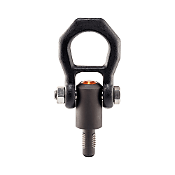
Perni di sollevamento per fori filettati, Autobloccanti
Fare clic sull'immagine per ingrandirla.
Cliccare sull´immagine per ingrandirla.
Tutte le versioni sono protette dalla corrosione. La versione in acciaio inossidabile però, oltre alla corrosione, è resistente agli agenti atmosferici, ed è quindi adatto anche per uso esterno. Inoltre, il perno ad alta resistenza temprato e indurito per cadute accidentali, è ideale anche per carichi estremi.
[Funzionamento]
The threaded elements are unlocked by pressing the button.
Codice componente
Qui sono indicati i codici componente
correlati al prodotto ricercato
Threaded Lifting Pins • self-locking, EH 22352.
Product Description
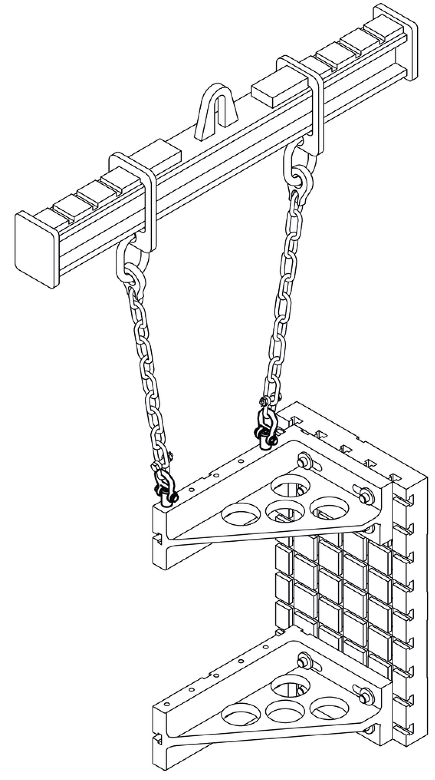
 | Heavy-duty lifting element for quick and easy use, with moveable shackle and locking stud to provide protection against unintentional unlocking. For lifting loads, the threaded lifting pin is inserted into a threaded hole. In contrast to a ringbolt, time-consuming screwing in and out is therefore unnecessary. All versions are corrosion-protected. The version made of stainless steel is also resistant to corrosion and weathering, so it is also suitable for external use. In addition, the high-strength, precipitation-hardened pin makes extreme loads possible. |
Material
• Heat-treated steel, tempered, manganese phosphated
• Stainless steel 1.4542, precipitation-hardened
Press button
• Aluminium, orange, anodised
Threaded element
• Stainless steel 1.4542, precipitation-hardened
Shackle
• Heat-treated steel, tempered, manganese phosphated
• Stainless steel 1.4571
Spring
• Stainless steel
Assembly
Mounting:
1. Press in the button and hold it down.
2. Insert the threaded lifting pin.
3. Release the button (The button must be back in its original position.).
4. Tighten the threaded lifting pin by hand, until it bears completely on the bearing surface.
5. It must be ensured that the threaded segments are engaged in the mounting thread.
Dismantling:
1. Unscrew the threaded lifting pin approx. a quarter of a turn anticlockwise.
2. Press in the button and hold it down.
3. Remove the threaded lifting pin.
4. Release the button.
Operation
Further products
• Lifting Pins, self-locking, stainless steel
• Threaded Lifting Pins, self-locking, for centre holes according to DIN 332
• Threaded Lifting Pins, self-locking, with rotatable shackle
• Threaded Lifting Pins, self-locking - INCH
• Threaded Lifting Pins, self-locking, with rotatable shackle - INCH
Drawing

Order Information
| Dimensions | Load capacity1) | Locating thread | Operating temperature range max. | Weight | Art. No. | ||||||||||||||
| d1 | l1 | d2 | d3 | l2 | l3 | l4 | l5 | l6 | l7 | l8 | l9 | l10 | F1 | F2 | F3 | ||||
| -0.07 | |||||||||||||||||||
| [mm] | [kN] | [mm] | [°C] | [g] | |||||||||||||||
| Heat-treated steel | |||||||||||||||||||
| M 8 | 12 | 6.62 | 21.5 | 17.8 | 25.7 | 36 | 27.0 | 30.0 | 49 | 87.5 | 21.5 | 8 | 2.1 | 0.9 | 0.8 | M 8 | 250 | 274 | 22352.0008 |
| M10 | 14 | 8.35 | 21.5 | 20.0 | 25.7 | 36 | 27.0 | 30.0 | 49 | 87.5 | 21.5 | 10 | 3.9 | 1.5 | 1.5 | M10 | 250 | 268 | 22352.0010 |
| M12 | 17 | 10.07 | 21.5 | 24.0 | 25.7 | 36 | 27.0 | 30.0 | 49 | 87.5 | 21.5 | 12 | 6.2 | 2.5 | 2.3 | M12 | 250 | 273 | 22352.0012 |
| M14 | 17 | 11.80 | 21.5 | 24.0 | 25.7 | 36 | 27.0 | 30.0 | 49 | 87.5 | 21.5 | 12 | 7.8 | 4.2 | 2.9 | M14 | 250 | 279 | 22352.0014 |
| M16 | 17 | 13.80 | 21.5 | 24.0 | 25.7 | 36 | 27.0 | 30.0 | 49 | 87.5 | 21.5 | 12 | 8.4 | 4.5 | 4.2 | M16 | 250 | 284 | 22352.0016 |
| M20 | 22 | 17.25 | 30.0 | 30.0 | 36.5 | 52 | 32.6 | 36.0 | 56 | 114.0 | 26.0 | 17 | 16.6 | 7.7 | 5.8 | M20 | 250 | 586 | 22352.0020 |
| M24 | 27 | 20.70 | 36.0 | 36.0 | 42.0 | 60 | 50.6 | 49.8 | 82 | 152.0 | 36.0 | 22 | 23.0 | 11.1 | 8.6 | M24 | 250 | 1187 | 22352.0024 |
| M27 | 31 | 23.67 | 45.0 | 40.0 | 42.0 | 60 | 50.6 | 49.8 | 82 | 152.0 | 36.0 | 26 | 33.8 | 15.7 | 13.7 | M27 | 250 | 1546 | 22352.0027 |
| M30 | 35 | 26.10 | 45.0 | 45.0 | 42.0 | 60 | 50.6 | 49.8 | 82 | 152.0 | 36.0 | 30 | 42.3 | 21.5 | 15.5 | M30 | 250 | 1596 | 22352.0030 |
| Stainless steel | |||||||||||||||||||
| M 8 | 12 | 6.62 | 21.5 | 17.8 | 25.7 | 36 | 27.0 | 30.0 | 49 | 87.5 | 21.5 | 8 | 2.1 | 0.9 | 0.8 | M 8 | 250 | 228 | 22352.1008 |
| M10 | 14 | 8.35 | 21.5 | 20.0 | 25.7 | 36 | 27.0 | 30.0 | 49 | 87.5 | 21.5 | 10 | 3.9 | 1.5 | 1.5 | M10 | 250 | 273 | 22352.1010 |
| M12 | 17 | 10.07 | 21.5 | 24.0 | 25.7 | 36 | 27.0 | 30.0 | 49 | 87.5 | 21.5 | 12 | 6.2 | 2.5 | 2.3 | M12 | 250 | 286 | 22352.1012 |
| M16 | 17 | 13.80 | 21.5 | 24.0 | 25.7 | 36 | 27.0 | 30.0 | 49 | 87.5 | 21.5 | 12 | 8.4 | 4.5 | 4.2 | M16 | 250 | 247 | 22352.1016 |
| M20 | 22 | 17.25 | 30.0 | 30.0 | 36.5 | 52 | 32.6 | 36.0 | 56 | 114.0 | 26.0 | 17 | 10.0 | 7.7 | 5.8 | M20 | 250 | 519 | 22352.1020 |
| M24 | 27 | 20.70 | 36.0 | 36.0 | 42.0 | 60 | 50.6 | 49.8 | 82 | 152.0 | 36.0 | 22 | 23.0 | 11.1 | 8.6 | M24 | 250 | 1219 | 22352.1024 |
Application Example


Codice componente
|
|---|
| 22352.0020 |
| 22352.1020 |
| Codice componente | Relativo a |
Prezzo unitario standard
| Quantità minima d'ordine | Sconto volumi elevati | Misura nominale vite (M) | d2 (mm) | d3 (mm) | l1 (mm) | l2 (mm) | l3 (mm) | l4 (mm) | l5 (mm) | l6 (mm) | l7 (mm) | l8 (mm) | l9 (mm) | l10 (mm) | F1 (kN) | F2 (kN) | F3 (kN) | Filetto femmina (mm) | Gambo | Anello | Peso (g) | |
|---|---|---|---|---|---|---|---|---|---|---|---|---|---|---|---|---|---|---|---|---|---|---|---|---|---|
216.86 € | 1 | 3 giorni | M20 | 17.25 | 30 | 22.0 | 30.0 | 36.5 | 52.0 | 32.6 | 36.0 | 56.0 | 114.0 | 26.0 | 17.0 | 16.6 | 7.7 | 5.8 | M20 | Acciaio fosfatato al manganese | Acciaio fosfatato al manganese | 586 | |||
282.41 € | 1 | 3 giorni | M20 | 17.25 | 30 | 22.0 | 30.0 | 36.5 | 52.0 | 32.6 | 36.0 | 56.0 | 114.0 | 26.0 | 17.0 | 10.0 | 7.7 | 5.8 | M20 | Acciaio inox 1.4542 | Acciaio inox 1.4571 | 519 |
Loading...
Informazioni di base
| Temperatura max.(°C) | 250 | Pulsante | Alluminio, arancio, anodizzato | Elemento filettato | Acciaio inox 1.4542 |
|---|---|---|---|---|---|
| Molla | Acciaio inox |
Configura
Proprietà di base
-
d2(mm)
-
d3(mm)
-
l1(mm)
- 17.0
- 22.0
- 27.0
- 31
- 35.0
-
l2(mm)
- 24.0
- 30.0
- 36.0
- 40.0
- 45.0
-
l3(mm)
- 25.7
- 36.5
- 42.0
-
l4(mm)
-
l5(mm)
- 27.0
- 32.6
- 50.6
-
l6(mm)
- 30.0
- 36.0
- 49.8
-
l7(mm)
- 49.0
- 56.0
- 82.0
-
l8(mm)
-
l9(mm)
- 21.5
- 26.0
- 36.0
-
l10(mm)
- 12.0
- 17.0
- 22.0
- 26.0
- 30.0
-
F1(kN)
-
F2(kN)
- 4.2
- 7.7
- 11.1
- 15.7
- 21.5
-
F3(kN)
- 2.9
- 5.8
- 8.6
- 13.7
- 15.5
-
Filetto femmina(mm)
- M14
- M20
- M24
- M27
- M30
-
Gambo
- Acciaio inox 1.4542
- Acciaio fosfatato al manganese
-
Anello
- Acciaio inox 1.4571
- Acciaio fosfatato al manganese
-
Tipo
- 22352
-
Misura nominale vite (M)
-
Filtrare per tipo dati CAD
- 3D
Filtrare per giorni di spedizione standard
-
- Tutti gli articoli
- 2 giorni o meno
- 3 giorni o meno
Attributi opzionali
- Specifiche e dimensioni di alcuni componenti potrebbero non essere illustrate in modo esauriente. Per i dettagli esatti, consultare i cataloghi dei produttori .


